background image

ADVANCED REMOTE CONTROL SYSTEMS 

 PROFLAME GT-GTM-GTMF-GTMFS

9.

95

5.

09

 0

0  

(09)

       Subject to change without notice

w

w

w

.

s

i

t

g

r

o

u

p

.

i

t

0_I00_gtmf_cat_only 0-1   1

1/0/00   1.0.

Содержание GT

Страница 1: ...ADVANCED REMOTE CONTROL SYSTEMS PROFLAME GT GTM GTMF GTMFS 9 955 093 00 09 Subject to change without notice w w w s i t g r o u p i t 0 _I00_gtmf_cat_only 0 1 1 1 0 00 1 0 ...

Страница 2: ...odern hearth appliances The GTMS is configured to control the on off and flame height operation of the main burner provides for thermostatic control of the appliance and Split Flow dual burner control The control features an advanced Smart thermostat which automatically modulates the flame height optimizing room temperature management The Proflame GTMS system is specifically developed to be used t...

Страница 3: ...livolt Combination Gas Control PROFLAME Transmitter PROFLAME Receiver PROFLAME FMC 820 NOVA millivolt HI LOW Combination Gas Control GT only GTMF only 829 NOVA millivolt Combination Gas Control PROFLAME Transmitter PROFLAME Receiver PROFLAME FMC 820 NOVA millivolt HI LOW Combination Gas Control IGNITION BOARD 880 PROFLAME Combination Gas Control 885 PROFLAME Combination Gas Control GTMF GTMFS ONLY...

Страница 4: ...ies Ambient temperature ratings 0 to 50 C 32 to 122 F Radio frequency 315 MHz receiver Feature Icon PROFLAME GT GTM GTMS GTMF GTMFS Room Temperature Display Child Lock Low Battery On Off Thermostat Flame On Off only Flame On Off Modulation 6 Levels Smart Thermostat Fan Speed Control 6 Levels On Off Auxiliary Outlet 120V Constant Outlet 120V Split flow Indicates included Features 0 _I00_gtmf_cat_on...

Страница 5: ...ame Gas Valve 885 family also the 880 886 families are compatible 6 Pilot assembly 7 Split Flow Control optional 8 Proflame GT Series wiring harness to connect the Receiver to the FCM to the DFC wirings to the Gas valve stepper motor and to the Split Flow Control 9 Proflame DFC wiring harness to connect the DFC to the gas valve and to the pilot burner Supply voltage frequency 120 V 60 Hz Ambient t...

Страница 6: ...itter uses a streamline design with a simple button layout and informative LCD displaywith blue back light Fig 1 The transmitter is powered by 3 AAA type batteries A Mode key is provided to index between the features and a Thermostat key Is used to turn on off or index through thermostat functions Fig 1 2A 2B 2C 2D Fig 1 Proflame Transmitter Blue LCD display Up Down Arrow Key ON OFF Key THERMOSTAT...

Страница 7: ...lock out Room Temperature Set Point Temperature Level State Flame ON Thermostat OFF ON SMART Fan Fig 2C Transmitter LCD display Proflame GTMF configuration Transmission Aux ON Low battery alarm Child safety lock out Room Temperature Set Point Temperature Level State Flame ON Thermostat OFF ON SMART Fan Fig 2D Transmitter LCD display Proflame GTMFS configuration Transmission Aux ON Split flow 0 _I0...

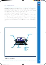
Страница 8: ...Remote Remote control or OFF receiver Fig 3 Proflame Receiver body 12 PIN terminal Fig 4 Fan Control Module Fan Control Module FCM offers the added ability to control the fan speed from off through six 6 speeds a remotely actuated 120V outlet and a constantly powered 120V outlet The FCM provides DC power to the receiver allowing the batteries to be used only in the event of line power loss Fig 4 F...

Страница 9: ...mbly and an automatic valve of the Proflame 880 886 and 885 families using low electric power The DFC Board can be powered by an AC DC wall adaptor and battery pack for back up Stand Alone System When used with the Proflame Remote System with or without a split flow valve the DFC Board can be powered by an AC DC wall adaptor via specific wire harness using the receiver batteries for back up GTM Sy...

Страница 10: ...r 2 Install the 4 AA type batteries in the battery compartment with the correct polarity 3 Make sure the receiver and cover plate words ON and UP are on the same side 4 Place the slider into the cover plate 5 Align the slider with the switch on the receiver and couple the switch into the slider 6 Using the two 2 screws provided secure the cover plate to the receiver Fan Control module Proflame GTM...

Страница 11: ...dc STABILIZED SUPPLY OUTPUT MOTOR IPI CPI RECEIVER DC SUPPLY SPLIT FLOW ON OFF TH TPTH DFC SUPPLY DC SUPPLY GROUND 885 PROFLAME Orange Green Chassis connection Remote control Fig 6C Proflame GTMF GTMFS 885 PROFLAME wiring diagram GTMS only REMOTE REMOTE 120V OUT Receiver 14 Pin Connector Split Flow Pilot Pink Blue CPI IPI MODE MOTOR IPI CPI RECEIVER FCM COM SPLIT FLOW ON OFF TH TPTH DFC SUPPLY DFC...

Страница 12: ...complete the ignition sequence for the Pilot Flame and then will remain with the Pilot Flame ON waiting for a command to ignite the Main Burner Flame Turning ON the Appliance Close the ON OFF command contact on the ON OFF wires and this will command the DFC ignition board to Turn ON the appliance s main burner Turning OFF the Appliance Open the ON OFF command contact on the ON OFF wires and this w...

Страница 13: ...Pilot ignition mode is selected the Pilot ON Flame will remain To also turn it completely OFF switch the appliance into Intermittent Pilot ignition mode so set the IPI CPI Pilot Mode Switch to the IPI position switch opened Initializing the System for the first time Install the 4 AA batteries into the receiver battery bay Note the polarity of the battery and insert into the battery bay as indicate...

Страница 14: ...he flame height each time it is pressed If the Up Arrow Key is pressed while the system is on but the flame is off the flame will come on in the high position Fig 9A 9B 9C 9D A single beep will confirm reception of the command Fig 8 Fig 9A Flame Off Fig 9B Flame Level 1 Fig 9 Fig 9C Flame level 5 Fig 9D Flame Level Maximum Fig 9 Fig 9E Fig 9F Split flow function GTMS GTMFS only The secondary burne...

Страница 15: ...emperature press the Up or Down Arrow Keys until the desidered set temperature is displayed on the LCD screen of the Transmitter Fig 13 Fig 12 Smart flame function Fig 13 Room Thermostat Transmitter Operation The Remote Control can operate as a room thermostat The thermostat can be set to a desired temperature to control the comfort level in a room To activate this function press the Thermostat Ke...

Страница 16: ...p will confirm the reception of the command Fig 16 Fig 17 Fig 14 Fan Speed Control Proflame GTMF GTMFS only If the appliance is equipped with a hot air circulating fan the speed of the fan can be controlled by the Proflame system The fan speed can be adjusted through six 6 speeds To activate this fun ction use the Mode Key fig 1 to index to the fan control icon Fig 14 Use the Up Down Arrow Keys fi...

Страница 17: ...r of ignitions of the appliance the number of changes to the room thermostat set point etc When the receiver batteries are low No beep will be emitted from the receiver when it receives an On Off command from the transmitter This is an alert for a low battery condition for the receiver When the batteries are replaced the beep will be emitted from the receiver when the ON OFF key is pressed See Ini...

Страница 18: ...urner will Turn ON Manual override Command definitions Pilot IPI CPI switch Position of the receiver slider switch Command reference name Commanded Fireplace State Opened IPI OFF REMOTE and OFF received Turn OFF Flames OFF Opened IPI ON REMOTE and ON received Turn ON Pilot Main burner flames ON Closed CPI OFF REMOTE and OFF received Pilot ON Pilot flame ON Closed CPI ON REMOTE and ON received Turn...

Страница 19: ...llimeters PROFLAME Transmitter PROFLAME Receiver PROFLAME FCM 70 36 140 70 36 37 70 36 71 PRG PRG 102 42 115 70 REMOTE REMOTE PRG PRG 102 42 115 70 REMOTE REMOTE Wall mounted DFC Control Board Hearth mounted 0 _I00_gtmf_cat_only 0 1 1 1 0 00 1 1 ...

Страница 20: ...SIT La Precisa S p A Viale dell Industria 31 33 35129 PADOVA ITALY Tel 39 049 829 31 11 Fax 39 049 807 00 93 www sitgroup it e mail mkt sitgroup it 0 _I00_gtmf_cat_only 0 0 0 1 0 00 1 1 ...

Отзывы: