SiRFatlasV
Hardware Design Guide
January, 2010
SiRF Design Guide
– Proprietary and Confidential
7
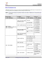
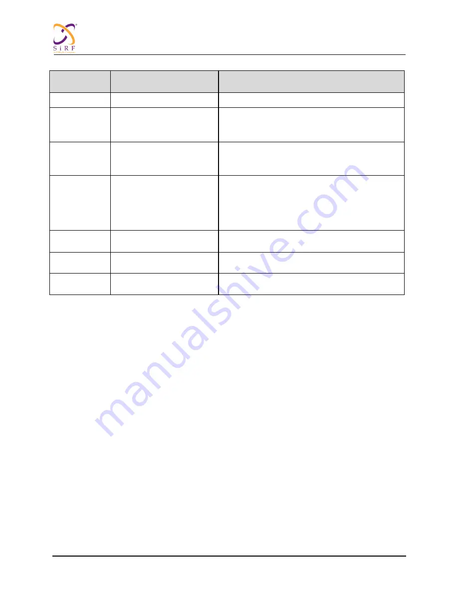
Spec and Configuration
Application
DCDC1
1.8v/2.5v, 500mA
Memory power supply
DCDC2
1.2v, 700mA
CPU core power supply
USB core
TSC core power supply
LDO1
3.3V, 100mA
TSC
ADC
USB analog power
LDO2
3.3V, 150mA
VDDIO
VDDIO_N
VDDIO_L
VDDIO_DAC
VDDIO_OSC
LDO3
1.2V, 10mA
PLL pad power supply
LDO4
3.3v,50mA
GPS power supply
LDO5
3.3V
VDDIO_RTC
Table 3: On-Chip PMU Specifications and Applications
M
ODAC
Refer to
CS-130255-UG SiRFatlasV Audio Hardware Design Guide
for the Modac design.
UART
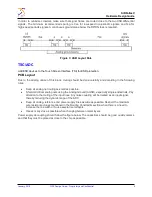
There are two UARTs on the SiRFatlasV chip, but only UART0 has the DMA function.
Use UART0 to
transmit large amounts of data at high speed.
UART0 has a hardware flow control function.
UART1 must be used as the debug port.
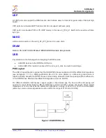
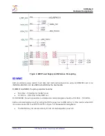
I
2
C
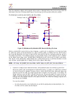
Add pull-up resistors to all I
2
C pins.
If there are many I
2
C devices on one bus, do not release the bus without powering on some of the
devices, otherwise the bus will hang. In this scenario, use GPIO to simulate the I
2
C bus.


