Simrad S3009 Скачать руководство пользователя страница 16

Color

Strong and weak signals have different colors to indicate the different signal strengths. The
colors used depend on which palette you select. The more you increase the Color setting,
the more echoes are displayed in the color at the strong return end of the scale.
To set the Color:

press the Color softkey once, then turn the rotary knob to adjust the value.
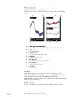
Display time 

You can change the length of the depth history shown on the display. This does not affect
already collected data, so the length of depth history shown will gradually change from the
old to the new value when changing display time.
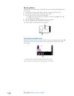
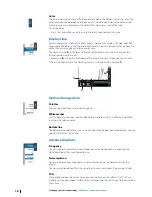
The numeric value (

A

) in the lower-left corner of the panel always shows the age of the

leftmost column on the screen.
A zebra scale (

B

) is shown at the bottom of the image, and each stripe equals one minute.

If there is a discontinuity in the depth signal, this is indicated with a triangle (

C

).

A

B

C

16

Optional image items

Palettes

You can select between several display palettes.

White marker

Use this option to change a specific color on the image to white. This effectively highlights


(or hides) the selected color.

Bottom line

The bottom line option makes it easier to distinguish the bottom from other objects. You can


specify the thickness of the line.

Advanced options

Frequency

The unit supports several transducer frequencies. Available frequencies depend on the


transducer model that is configured for use.

Noise rejection

Signal interference from bilge pumps, engine vibration and air bubbles can clutter the


image.
The noise rejection option filters the signal interference and reduces the on-screen clutter.

TVG

Wave action and boat wakes can cause onscreen clutter near the surface. The TVG (Time


Variable Gain) option reduces surface clutter by decreasing the sensitivity of the receiver near


the surface.

Setting up the echosounder image

 | S3009 Echo Sounder User


Manual

Содержание S3009

Страница 1: ...ENGLISH S3009NavigationEchoSounder User Manual www navico commercial com...

Страница 2: ......

Страница 3: ...product Documentation may be translated to or has been translated from another language Translation In the event of any conflict between any Translation of the Documentation the English language versi...

Страница 4: ...operators and installers It assumes that the user has basic knowledge of echosounders and assumes some knowledge and skills relevant to installation of transducers and echosounder equipment Software...

Страница 5: ...l pages Use the rotary knob Zoom in out Use the and keys Maneuver on a page that is larger than the display area Use the arrow keys Exit the PDF viewer Use the Exit key Trademarks Navico is a register...

Страница 6: ...nder image 15 Setting the range 15 Adjusting color and gain settings 16 Display time 16 Optional image items 16 Advanced options 18 Panel setup 18 Selecting transducer source 18 Split screen options 1...

Страница 7: ...log 38 Access control 38 System settings 39 Echo settings 41 Units settings 41 Network settings 45 Maintenance 45 Preventive maintenance 45 Cleaning the display unit 45 Cleaning the media port door 45...

Страница 8: ...ble at the product web site www navico com commercial System components S3009 Control unit The S3009 is a dedicated echosounder control unit with a 9 inch portrait display The unit is fitted with a hi...

Страница 9: ...n With cursor active press to remove cursor Menu operation press to return to previous menu level or to exit a dialog 5 Rotary knob With no menu active behavior depending on operational mode Menu oper...

Страница 10: ...istory shown on the display F Instrument bar Two configurable data gauges G Alerts panel List of active alerts Softkeys When a softkey is pressed the function for the selected softkey becomes availabl...

Страница 11: ...the up down arrow keys to adjust the value Settings dialogs The various Settings dialogs provide access to system settings You access the Settings dialogs from the Main menu Note Some of the paramete...

Страница 12: ...lerts softkey is labelled Alerts Acknowledge Alerts Ack on smaller screens if there is an unacknowledged alarm or warning in the system Acknowledge the most recent alert by pressing the Alerts softkey...

Страница 13: ...ing the image You zoom the image by pressing the Zoom softkey and then turning the rotary knob You can pan the zoomed area with the arrow keys The zoom level is shown in the Zoom softkey You can also...

Страница 14: ...Information window 4 Press the Enter key to switch reference point to cursor position 5 Continue selecting new measuring points if required Press the Fin softkey to exit the measurement feature A B V...

Страница 15: ...ce to display the pop up and then selecting the Custom option Note Setting a custom range puts the system in manual range mode Adjusting color and gain settings Gain The gain controls the sensitivity...

Страница 16: ...n the depth signal this is indicated with a triangle C A B C 16 Optional image items Palettes You can select between several display palettes White marker Use this option to change a specific color on...

Страница 17: ...he rate the transducer transmits the signal into the water By default the ping speed is set to max It may be necessary to adjust the ping speed to limit interference Setting up the echosounder image S...

Страница 18: ...arranged on top of each other or side by side Gain and color icons B are displayed on dual panels Press the rotary knob to switch focus between the panels Active panel is indicated with a border Zoom...

Страница 19: ...hide menu option to immediately hide the softkey bar Pressing any softkey re displays the softkey bar Auto hide the softkey bar Selecting the auto hide option will hide the softkey bar after a few sec...

Страница 20: ...e Files dialog You can copy rename and delete files You can transfer files from the unit to a memory card in the card reader and vice versa using the copy option Simulator The simulation feature lets...

Страница 21: ...and data will be recorded until the SD card is full At this time the oldest log file will be deleted Alert log An alert log is stored internally The log contains time time source alert ID alert text...

Страница 22: ...rm before caution then age Alarms have different states Active not acknowledged not silenced Active acknowledged Rectified not acknowledged When an alert has been both rectified and acknowledged it wi...

Страница 23: ...lude a time stamp Alphabetic alert list Alert type abbreviations C Caution A Alarm Alert text Description Type BAM heartbeat lost No HBT message is received Only relevant if one or more NMEA 0183 port...

Страница 24: ...F G H I E D A Control unit B Bezels C Transducer cable D Power cable E Document package F NMEA 0183 cable G U bracket mounting kit H Panel mounting kit I Junction kit U bracket mounting 1 Place the b...

Страница 25: ...te Transducers The ideal mounting location for transducers depend on the design of the vessel The installation shipyard must ensure sufficient reinforcement and watertightness of the hull and must des...

Страница 26: ...heat shrink Protect joints from water humidity and otherwise corrosive environments leave enough space for connecting and disconnecting cables Warning Before starting the installation be sure to turn...

Страница 27: ...required between the transducer and the S3009 or S5100 module For dual transducer installations an S5100 module has to be installed E D A B C E G F B C A S3009 7 pin transducer cable B Optional exten...

Страница 28: ...hite 2 Black 3 Shield 1 Unknown color 2 Unknown color 3 Shield Depth GND Depth Depth 1 Unknown color 2 Unknown color 3 Shield Depth GND Depth Depth Optional extension cable B 7 pin connector Transduce...

Страница 29: ...th Depth Optional extension cable B Transducer Junction E Junction G 9 pin connector F C Note For more details refer to Extensioncable on page 28 and Junctiondetails on page 30 Echosounder 9 pin conne...

Страница 30: ...e according to dimensions Push back the cable s braided shield Remove insulation from the conductors Connect the conductors with crimp joiners using a professional crimp tool Seal the joint with self...

Страница 31: ...cable Remove the aluminum foil that surrounds the wires Separate the wires to be used from the other wires Remove insulation from the conductors to be used Connect the conductors to be used with crim...

Страница 32: ...t be used Remove the plastic stoppers Insert the spacers if the cable diameter is less than 9 5 mm Use an optional junction box sold separately if the cable diameter exceeds 12 0 mm Place the cable an...

Страница 33: ...and over voltage for a limited duration A fuse or circuit breaker should be fitted to the positive supply For recommended fuse rating refer to the technical specification in the Appendix on page 47 A...

Страница 34: ...Transmit positive TX 2 Transmit negative TX 3 Receive positive RX 4 Receive negative RX 5 Shield NMEA 0183 wiring The NMEA 0183 serial port provides input Listeners and outputs Talkers for the variou...

Страница 35: ...reen 5 Orange White 6 Orange 7 Blue White 8 Blue Talkers and Listeners Do not connect multiple devices outputting data Talkers on to any serial input RX of the unit The RS422 protocol is not intended...

Страница 36: ...wiring The external alarm is connected through the power connector NC Isolated Alarm Circuit Low Voltage Alarm Bridge Alert System Power connector details 3 4 1 2 Unitsocket male 1 2 3 4 Cableplug fem...

Страница 37: ...xternal alarm A B C Key Purpose Color A External alarm output negative return Yellow B External alarm output N C isolated contact Blue C Alert management system Wiring S3009 Echo Sounder User Manual 3...

Страница 38: ...nder settings Configure the transducer s from the Echo Installation dialog Source name keel offset and transducer type should be configured for all connected transducers Refer to Echosettings on page...

Страница 39: ...a value for the magnetic variation Optimize for left hand view Select this option to optimize the display for viewing from the left About Displays copyright information software version and technical...

Страница 40: ...res data on the NMEA 2000 network and on the NMEA 0183 DPT sentence Installation Source Select this option to display a list of Echosounder sources available for setup The settings you make in the res...

Страница 41: ...he Network settings dialog to setup networks and connect to network devices Info Displays the Ethernet connection status the unit s IP and MAC addresses Device name Assigning a name is useful in syste...

Страница 42: ...tions specific to the device Note Setting the instance number on a 3rd party product is typically not possible Diagnostics The NMEA 2000 tab on the diagnostics page can provide information useful for...

Страница 43: ...of units The function is used on larger vessels where several SimNet units are connected to the network By assigning several units to the same group a parameter update on one unit will have the same...

Страница 44: ...sed default mode Standard in this mode the output sentences can be manually configured BAM select to communicate with an external Bridge Alert Management system conforming to IEC 61924 2 Legacy alerts...

Страница 45: ...age the anti glare layer or plastic bezel To prevent UV damage to the plastic bezel it is recommended that the sun cover be fitted when the unit is not in use for an extended period Cleaning the media...

Страница 46: ...aluable user data Backing up your system data It is recommended to regularly copy your system settings files as part of your back up routine The files can be copied to a card inserted in the card read...

Страница 47: ...g softkey Symbols used access sub menu open dialog Softkey Menu level 1 Menu level 2 Menu Alerts Depth below Alarm depth Draft Files Edit Instrument bar Softkey bar Hide Auto hide Settings View Source...

Страница 48: ...iew About Echo Network sonar Internal echosounder Network mode Restore sonar defaults User depth data from Installation Alerts Siren enabled Alerts Units Distance Distance small Wind speed Speed Depth...

Страница 49: ...Dimensional drawings Dimensions S3009 Control unit 247 mm 9 72 224 mm 8 81 219 mm 8 62 80 mm 3 14 67 mm 2 63 100 mm 3 93 280 mm 11 02 260 mm 10 23 Appendix S3009 Echo Sounder User Manual 49...

Страница 50: ...0 200 xxL transducers 69 5 mm 2 74 88 5 mm 3 48 40 mm 1 58 R 8 mm 0 31 R 4 mm 0 16 20 mm 0 79 60 mm 2 36 60 mm 2 36 20 m 65 62 55 mm 2 17 5 mm 0 2 22 mm 0 87 25 mm 0 98 3 mm 0 12 15 mm 0 59 50 Appendi...

Страница 51: ...Variation x x HDM Heading Magnetic x HDT Heading True x MOB Man Over Board x MTW Water Temperature x x MWD Wind Direction and Speed x x MWV Wind Speed and Angle x x OSD Own ship data x RMC Recommended...

Страница 52: ...id Level 127506 DC Detailed Status 127507 Charger Status 127508 Battery Status 127509 Inverter Status 128259 Speed Water referenced 128267 Water Depth 128275 Distance Log 129025 Position Rapid Update...

Страница 53: ...ure 130576 Small Craft Status 130577 Direction Data 130578 Vessel Speed Components NMEA 2000 PGN transmit 126208 ISO Command Group Function 126992 System Time 126996 Product Info 127237 Heading Track...

Страница 54: ...en brightness 1200 cd m2 Viewing angles 160 horizontal 110 vertical Electrical Supply voltage 10 8 31 2 V DC Power consumption Max 12 W Power consumption Typical 11 W Recommended fuse rating 3 A Envir...

Страница 55: ...requency 50 kHz Beam width 44 Max depth 1 500 m 4 921 ft Speed 30 knots 35 mph Technical specifications TGM50 200 xxL transducer Physical Dimensions See Dimensions TGM60 50 xxLandTGM50 200 xxL transdu...

Страница 56: ...988 12043 001 www navico com commercial...

Отзывы: