579-1203 Installation Instructions
579-1203
Rev. B
R
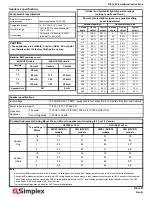
Appliance specifications
Environmental specifications
Rated DC control/strobe
voltage range
Special application 23-30 VDC
Temperature range
32 °F to 120 °F (0 °C to 49 °C)
Humidity range
10 % to 93 %, non-condensing at
104 °F (40 °C)
Connections
Terminal for 18 AWG to 12 AWG
(0.82 mm
2
to 3.31 mm
2
)
CAUTION:
• The appliances are available in red and white. Do not paint
or otherwise alter the factory finishes in any way.
Maximum RMS operating current
49[SV/HFV] visible
49[SVH/HFVH] visible
Candela
Current
Candela
Current
15
59 mA
-
-
30
82 mA
110
235 mA
75
145 mA
135
255 mA
110
193 mA
185
295 mA
Speaker Only
SO
9 mA
Vertical and horizontal light dispersion ratings
(ceiling to walls and floors)
Percent of rated light output at any candela setting
(room temperature)
Vertical dispersion
Horizontal dispersion
Y-plane
angle
UL req
output
Typical
output
X-plane
angle
UL Req
output
Typical
output
0
100
%
327
%
0
100
%
343
%
±5
90
%
293
%
±5
90
%
160
%
±10
90
%
281
%
±10
90
%
175
%
±15
90
%
197
%
±15
90
%
129
%
±20
90
%
168
%
±20
90
%
145
%
±25
90
%
142
%
±25
90
%
165
%
±30
45
%
143
%
±30
45
%
152
%
±35
45
%
155
%
±35
45
%
144
%
±40
45
%
156
%
±40
45
%
139
%
±45
45
%
134
%
±45
45
%
129
%
±50
55
%
115
%
±50
55
%
129
%
±55
45
%
104
%
±55
45
%
123
%
±60
40
%
103
%
±60
40
%
111
%
±65
35
%
98
%
±65
35
%
120
%
±70
35
%
87
%
±70
35
%
103
%
±75
30
%
90
%
±75
30
%
75
%
±80
30
%
96
%
±80
30
%
83
%
±85
25
%
96
%
±85
25
%
70
%
±90
25
%
83
%
±90
25
%
47
%
Speaker specifications
Input voltage
25 VRMS or 70.7 VRMS - speakers are for connection to compatible fire alarm audio circuits.
Power taps via jumper J1
1/4 W, 1/2 W, 1 W and 2 W
Frequency
Response
Fire alarm
400 Hz to 4000 Hz [SV/SO]; 200
Hz to 10000
Hz [HFV/HF]
General signaling
125
Hz to 12
kHz
TrueAlert Addressable Ceiling Mount S/V and SO units- speaker switch setting (25 V or 70 V audio)
-
Tap settings in
Watts
UL1480 at 10 ft
ULC-S541 at 3 m
HiSPL (SV/SO)
models
HiFi (HFV/HF)
models
HiSPL (SV/SO)
models
HiFi (HFV/HF)
models
Speaker
Only
1/4
79
77
81
78
1/2
83
81
85
82
1
86
84
88
85*
2
90
87
91
88*
Speaker
Visible
1/4
79
76
79
78
1/2
83
80
83
82
1
86
84
86
85*
2
89
87
89
88*
Note:
•
Reverberant dBA measurements are a minimum UL rating based on sound level measurements made in UL’s reverberant test chamber.
•
Anechoic dBA measurements are a minimum ULC rating based on sound pressure level measurements made in ULC’s anechoic test chamber.
•
The sound pressure level decreases by 3 dB at an angular displacement of 70° from the line perpendicular to the speaker’s center. The SPL
decreases by 6
dB at an angle of 80° from that line.
•
Only marked settings may be used for ULC fire alarm applications.


