18
Table 3. Inlet Tube Selection
OVERALL DUCT
WIDTH
TUBE REQUIRED
TUBE TYPE
SUGGESTED TOTAL
LENGTH
12 inches (30 cm)
2098-9796
Hole
13 inches (33.02. cm)
½ inch (1.27 cm)
longer than duct width
13 inches (33.02 cm) to
23 inches (58 cm)
2098-9804
Hole
24 inches (60.96 cm)
½ inch (1.27 cm)
longer than duct width
24 inches (60 cm) to
46 inches (1.16 m)
2098-9797
Hole
49 inches (125.46 cm)
2 inches (5.8 cm)
longer than duct width
46 inches (1.16 m) to
71 inches (1.8 m)
2098-9798
Hole
73 inches (1.85 m)
2 inches (5.8 cm)
longer than duct width
71 inches (1.8 m) to
95 inches (2.4 m)
2098-9799
Hole
97 inches (2.45 m)
2 inches (5.8 cm)
longer than duct width
Housing Installation
5
.
Insert the inlet and exhaust tube receptors of the housing base into the two
holes previously cut in the duct.
6. Using the four # 8 self-tapping sheet metal screws provided in the accessory
kit, locate the four mounting hole locations that are marked inside on the
duct housing plastic (Detector Chamber marked “MTG”). Drill the four
self-tapping screws through the housing plastic and duct sheet metal to
secure the duct housing (no pre-drilling is required). Torque screws 10-12
inch-pounds.
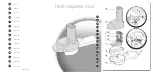
Inlet Tube Installation (See Figures 13 and 14)
7. Install the inlet tube by inserting the rubber plug end of the tube into the
upstream tube receptor located in the rear of the duct housing. The inlet
tube must be installed through the hole in the housing corner next to the
smoke port/air flow test holes. Place the tube retainer (supplied) over the
inlet tube so that the tab on the tube retainer goes into the slot on the inlet
tube. Make sure the tube retainer is in the proper orientation so that the
holes in the inlet tube face upstream into the airflow. The tab on the inlet
tube retainer bracket indicates the inlet hole side of the pipe.
Note:
If a support hole is being used, be sure to insert the inlet tube through
the hole on the far side of the duct.
8. Fasten the tube retainer using two #8 machine screws.
Notes:
1. Be sure to securely tighten the #8 machine screws to prevent accidental
turning of the tube within the receptor. Torque screws 16-18 inch-pounds.
2. If the inlet protrudes through the far side of the duct, seal the opening around the
tube (on the outside of the duct) with duct sealant.
Exhaust Tube Installation (See Figures 13 and 14)
9. Install the exhaust tube into the downstream receptor of the duct housing
base. Place the inlet tube retainer bracket (supplied) over the exhaust tube
so that the tab on the tube retainer goes into the slot on the exhaust tube.
10. Fasten the tube retainer using two #8 machine screws.
Note:
Be sure to securely tighten the #8 machine screws. Torque screws
16-18 inch-pounds.
Continued on next page
Installation,
Continued
Duct Detector/Sensor
Installation,
(continued)
Technical Manuals Online! - http://www.tech-man.com
Содержание 4098-9685
Страница 2: ...Blank Page Technical Manuals Online http www tech man com...
Страница 4: ...Blank Page Technical Manuals Online http www tech man com...
Страница 6: ...BLANK PAGE Technical Manuals Online http www tech man com...
Страница 32: ...BLANK PAGE Technical Manuals Online http www tech man com...
Страница 33: ...BLANK PAGE Technical Manuals Online http www tech man com...
Страница 34: ...BLANK PAGE Technical Manuals Online http www tech man com...
Страница 35: ...BLANK PAGE Technical Manuals Online http www tech man com...