background image

22

Dn

Dial Command. This command directs the modem to
go off-hook, wait for a dialtone, and dial the number
indicated in the dial string, n. The dial string may
contain the characters 0-9 for pulse-mode dialing or 0-9,
A-D, *, and # for touch-tone dialing. Spaces, hyphens,
and parentheses can be included in the command to
improve readability. For example, D (123) 456-7890 and
D1234567890 are equivalent.

In addition, the dial string may contain these dial com-
mand modifiers:

L

Redial the last valid number entered.

P

Pulse-mode dialing. (See S14.)

T

Touch-tone dialing. (See S14.)

S=n Dial 1 of 4 stored telephone number, where n is 0, 1,

2, or 3. (See &Zn)

W

Wait for a second dialtone. (See S7.)

 ,

Pause before dialing the digits that follow. (See S8.)

@

Wait for quiet answer. Wait for one or more rings
followed by at least five seconds of silence before
continuing with execution of the dial string. This is
useful for transferring calls on some PBX systems.

 ;

Return the modem to command state. When placed
at the end of the dial string, this puts the modem
into command mode. While in command mode, the
modem will not attempt to connect with the remote
modem.

Содержание STI-FAX/28.8

Страница 1: ...i Document Part Number 61000 00228 000 28 8 Communicator V 34 Data Fax Modem Plug n Play PC Card User Guide ...

Страница 2: ...ii 1 800 367 7330 3001 Daimler Street Santa Ana California 92705 714 476 1180 714 476 1209 fax ...

Страница 3: ...iii 28 8 Communicator V 34 Data Fax Modem Plug n Play PC Card User Guide ...

Страница 4: ...e reproduced transmitted transcribed stored in a retrieval system or translated into any language or computer language in any form by any means electronic mechanical magnetic optical chemical manual or otherwise without expressed written consent of STI Disclaimer Specifications subject to change without notice Simple Technology Inc makes no representations or warranties with respect to the content...

Страница 5: ...e Hardware 5 The Software 7 Specifications 7 3 Installing the Card 9 Checking for Card and Socket Services 9 Attaching the Card 10 Installing the Communication Software 10 Configuring the Communication Software 11 4 Using the Card 13 Inserting or Removing Your Card 13 About Call Waiting 13 Connecting to Cell Phones 14 Protecting the Card 14 ...

Страница 6: ... 3 20 AT Commands 21 AT Commands 27 AT Commands 35 AT Commands 36 AT Commands 40 AT Commands 40 AT Commands 41 AT Commands 41 AT Commands 41 6 Fax and Voice Commands 43 7 Result Codes and Messages 45 8 S Registers 49 Example Writing to an S Register 53 Bit Mapped Options S Registers 53 Example Setting an S Register 54 Example Interpreting an S Register 55 ...

Страница 7: ... an incoming call In most but not all areas the total REN of devices connected to a line should not exceed five 5 0 To find out the total permitted in your area contact your local telephone company If your telephone equipment causes harm to the telephone network the telephone company may discontinue your service temporarily If possible the company will notify you in advance But if advance notice i...

Страница 8: ...f not installed and used in accordance with the instructions may cause harmful interference to radio communications However there is no guarantee that interference will not occur in a particular installation If this equipment does cause harmful interference to radio or television reception which can be determined by turning the equipment off and on the user is encouraged to try to correct the inte...

Страница 9: ...ertified connector assembly telephone extension cord The customer should be aware that compliance with the above conditions may not prevent degradation of service in some situations Repairs to certified equipment should be made by an authorized Canadian maintenance facility designated by the supplier Any repairs or alterations made by the user to this equipment or equipment malfunctions may give t...

Страница 10: ...pparatus as set out in the interfer ence causing equipment entitled Digital Apparatus ICES 003 of the Department of Communications Cet appareil numerique respecte les limites de bruits radio electriques applicables aux appareils numeriques de Classe B prescrites dans la norme sur le materiell brouilleur Appareils Numeriques NMB 003 edictee par le ministre des Communica tions Etiquette D Homologati...

Страница 11: ...use d un mauvais fonctionnement Pour sa propre protection l utilisateur doit s assurer que tous les fils de mise a la terre de la source d energie electrique des lignes telephoniques et des canalisations d eau metalliques s il y en a sont raccordes ensemble Cette precaution est particulierement importante dans les regions rurales AVERTISSEMENT l utilisateur ne doit pas tenter de faire ces raccorde...

Страница 12: ...xii Notes ...

Страница 13: ...r computer as an answering machine The PC Card works with PCMCIA Release 2 1 Type II specifica tions standard on most laptop and notebook computers The PCMCIA standard allows for easy hardware installation just plug the card into your computer card socket The card features Plug n Play allowing you to install the card with your computer power turned on The credit card size and easy installation of ...

Страница 14: ...pter 3 for instructions on installing the card 3 Refer to Chapter 4 for further information on using the card 4 Refer to the guide that is provided with the communica tion software for instructions on installation and start up of the communication software 5 Refer to the Chapters 5 to 8 for technical information on the modem AT commands and S Registers 6 Refer to the Connecting the STI Modem to Ce...

Страница 15: ...er microprocessor 2 MB of RAM An internal hard drive A 3 5 inch floppy drive The following operating systems MS DOS v5 0 or later and Windows v3 1 Card and Socket Services compatible to PCMCIA Release 2 1 specifications An available phone line A handset optional NOTE There is no industry standard for the signal polarity of handsets therefore the modem does not work with all handsets ...

Страница 16: ...tructions Connecting the STI Modem to Cell Phones flyer P N 61000 00062 xxx Communications Software and User Guide If any item is missing or damaged contact your dealer immedi ately Technical Support If you experience any difficulties with the installation of the card call Technical Support at the following telephone numbers 714 476 1180 1 800 367 7330 ...

Страница 17: ...d contains a connector for a PC Card socket and a connector for the Line Access Cable The card is encased in metal allowing for safe handling With Card and Socket Services provided with your computer the card features Plug n Play capability i e the ability to insert or remove the card with the computer power turned on The card is keyed and will install only in the proper orientation Connector for ...

Страница 18: ... during use To remove the cable from the card press on the latch release buttons on both sides of the connector The standard jack for the phone line is the wider jack connection with only two wires The jack for the optional handset is the narrower jack connection with four wires The handset is for use with the modem s voice capabilities NOTE There is no industry standard for the signal polarity of...

Страница 19: ...llowing specifications Form Factor Data Rates Fax Rates Data Compression Error Correction Data Command Set Fax Command Set PCMCIA Type II CCITT V 34 28800bps CCITT V 32bis 14400bps CCITT V 32 9600bps CCITT V 22bis 2400bps CCITT V 21 300bps CCITT V 23 1200 600bps forward 75bps backward Bell 212A 1200bps Bell 103 0 300bps CCITT V 17 14400bps CCITT V 29 9600bps CCITT V 27ter 4800bps CCITT V 42bis up ...

Страница 20: ... hook 975mW Standby mode on hook 40mW Operates on systems with PC DOS 5 0 or higher or MS DOS 5 0 or higher Windows 3 1 Card and Socket Services conforming to PCMCIA Card and Socket Services Release 2 1 or higher Enhanced UART interface provides buffering of data This feature is essential in providing reliable high speed communication when used in multi tasking environments like Windows MNP10 EC e...

Страница 21: ...ther PC Cards as well If you know that you already have Card and Socket Services Release 2 1 installed proceed to Attaching the Card If you do not know if you already have Card and Socket Services installed perform the following 1 While booting your computer press F8 With DOS 6 or higher this will load the drivers in CONFIG SYS one line at a time 2 When prompted press Y to load each driver and loo...

Страница 22: ...ower four wire jack in the Line Access Cable NOTE There is no industry standard for the signal polarity of handsets therefore the handset jack does not work with all handsets Proceed to Installing the Communication Software Installing the Communication Software Once you have installed your modem you can use the communications software to connect to remote computers dial bulletin boards send electr...

Страница 23: ...t and IRQ that Card and Socket Services assigns to your modem 2 You may have to edit the SYSTEM INI file of Win dows Before editing SYSTEM INI make a backup of SYSTEM INI Open SYSTEM INI with your favorite editor Find the same COM port that your modem uses as determined in Step 1 Then change the IRQ associated with that COM port so that it is the same as that determined in Step 1 Save the new SYST...

Страница 24: ...12 Notes ...

Страница 25: ...r communications are not interrupted while using your modem you should disable call waiting if you have call waiting The methods for disabling call waiting vary in different locations Instructions for disabling call waiting can usually be found in the front section of the local telephone directory If disabling call waiting is required you may want to incorporate the disabling feature into the stan...

Страница 26: ...to a cell phone substitute the cell phone cable for the line access cable and follow the instructions in Chapter 3 Protecting the Card Observe the following points Do not drop the card Do not open the card Never remove the card when the computer is accessing the card Place the computer and peripherals out of direct sunlight high or low temperatures and high humidity Do not turn the computer or per...

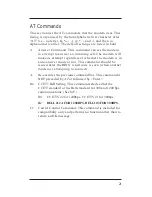
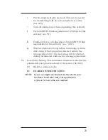
Страница 27: ...em must also be in command mode see Some Notes About AT Commands to accept AT command strings To verify whether your modem is in the proper mode type AT Enter If the modem responds with an OK message you are all set AT commands must 1 Start with the command string AT 2 Contain one or more of the commands listed in this chapter 3 End with a carriage return shown in this book as Enter The following ...

Страница 28: ...thod tone or pulse DT Dial the following number using tones DP Dial the following number using pulses DS n Dial stored number n W Wait for dial tone before dialing H Hang up the phone O Go on line switch from command mode to data mode Used to resume interrupted communications when the remote modem is still on line Sr Read S register r Sr n Write value n to S register r Zn Reset and recall saved pr...

Страница 29: ...ITT standard This feature can be useful if you wish to save space when issuing com mands If your modem is on line and you want to issue an AT command string to your modem without disrupting your connection you can bring your modem into command mode by typing a special escape sequence To issue the escape sequence you must first not transmit any data for a period equal to the guard time which by def...

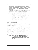
Страница 30: ...hapter These stored configurations are called profiles Not all AT command settings and S registers can be stored as a part of a profile The ones that can be stored are so noted Several sample modem configurations are shown below These are examples of profiles you might store in memory as your user definable profiles You can store two user defined profiles Sample Configuration 1 One useful configur...

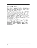
Страница 31: ...e up to 115200 bps Sample Configuration 2 If you are using software that does not support hardware flow control then you might use the following configuration AT F0 C1 D2 K4 Enter This configuration is identical to that of the previous example except that K4 is used to enable software flow control rather than hardware flow control Note that software flow control must be used with caution Do NOT us...

Страница 32: ...t flow control data compression or error correction J1 forces the data terminal equipment DTE rate to match the data communication equip ment DCE rate which is required when all flow control is disabled In this case you must set your terminal speed to match the line speed e g 14 4 Kbps This configuration is not reliable for high speed connections unless transferring files with newer XMODEM or ZMOD...

Страница 33: ...to answer mode or not This command should be issued after the RING result code is seen when another modem is attempting to connect A Re executes the previous command line This command is NOT preceded by AT or followed by Enter Bn CCITT Bell Setting This command selects either the CCITT standard or the Bell standard for 300 and 1200 bps communications See S27 B0 CCITT V 22 for 1200bps CCITT V 21 fo...

Страница 34: ...rs L Redial the last valid number entered P Pulse mode dialing See S14 T Touch tone dialing See S14 S n Dial 1 of 4 stored telephone number where n is 0 1 2 or 3 See Zn W Wait for a second dialtone See S7 Pause before dialing the digits that follow See S8 Wait for quiet answer Wait for one or more rings followed by at least five seconds of silence before continuing with execution of the dial strin...

Страница 35: ... call only see Mn Wait for credit card bong before continuing with the dial string If the bong is not detected within the time specified in S7 the dial string will be aborted dialing terminated and an error message generated En Local Echo Setting This command determines whether the commands you type are echoed to the screen See S14 E0 Disable command echo E1 ENABLE COMMAND ECHO NOTE If you see dup...

Страница 36: ...ing I5 Report country code e g 022 for U S I6 Report data pump model and code revision I7 Reports DAA code for external DAA if not in stalled reports 255 Ln Speaker Volume Setting See also register S22 On PCMCIA modems there may be no discernable difference between volume levels L0 Off L1 Low L2 Medium L3 High Mn Speaker Control Setting This command controls when the speaker will be on or off See ...

Страница 37: ...and determines whether or not the modem returns result codes such as OK ERROR or CONNECT See S14 S95 Vn Wn Xn Q0 Display result codes Q1 Do not display result codes Sn Read S register This command enables you to read the S register specified by the number n For example typing ATS0 Enter will allow you to view the contents of the S0 register Sn x Write to an S register This command allows you to ch...

Страница 38: ...e CARRIER 14400 PROTOCOL LAPM CONNECT 57600 W2 Report DCE rate only For example CONNECT 14400 Xn Extended Result Code Setting This command selects which call progress result codes are reported See S22 S95 Qn Vn Wn and Result Codes and Messages X0 Send basic call progress result codes OK CONNECT RING NO CARRIER ERROR NO ANSWER X1 Same as X0 but also report rate specific CONNECT messages X2 Same as ...

Страница 39: ...nfiguration profile 0 Z1 Perform modem reset and restore configuration profile 1 AT Commands Cn Carrier Detect CD Signal Setting See S21 C0 CD always on C1 CD follows state of carrier Dn Data Terminal Ready DTR Signal Setting This com mand affects the interpretation of the DTR signal Note that when the modem is on line it ignores a DTR drop that lasts less than the value in S25 05 seconds by defau...

Страница 40: ...n Telephone Jack Setting The J0 and J1 commands are included for compatibility only and perform no function other than to return an OK message Kn Flow Control Setting If your communications software does not support hardware flow control you will need to specify K0 or K4 see below See S39 K0 Disable flow control K3 Enable hardware flow control only K4 Enable software flow control only K5 Enable tr...

Страница 41: ... will determine whether or not a failure to establish a particular error correction link will result in the modem hanging up or trying to make another type of connection See also N2 N3 N4 and N5 Q6 Selects normal connection Equivalent to N0 Rn Hardware Flow Control Setting This command selects how the modem controls its Clear to Send CTS signal if hardware flow control is selected See S21 R0 CTS a...

Страница 42: ... a test will terminate automatically after the number of seconds specified in S18 T1 Local analog loopback test This test checks the operation of your modem s transmitter and re ceiver For example 1 Your modem should be on hook and in command mode Type AT N0 Enter This specifies a normal connection 2 Type AT S18 10 Enter This specifies a test period of 10 seconds 3 Type AT T1 Enter This initiates ...

Страница 43: ...t pressing Enter When you see the OK message your modem is in command mode 5 Issue the command AT T3 Enter This initiates the local digital loopback test 6 Have someone at the remote modem type a simple character pattern This character pattern then loops through your modem back to the remote modem Everything is working properly if the original character pattern is echoed back to the remote user s ...

Страница 44: ...Enter Wait for the CONNECT message 4 Issue the escape sequence to put the modem back into command mode type without pressing Enter When you see the OK message your modem is in command mode 5 Issue the command AT T6 Enter This initiates the remote digital loopback test Note that the remote modem must support CCITT V 54 and must be prepared to accept the request for this test See T4 6 Type a simple ...

Страница 45: ...or the CONNECT message 4 Issue the escape sequence to put the modem back into command mode type without pressing Enter When you see the OK message your modem is in command mode 5 Issue the command AT T7 Enter This initiates the remote digital loopback with self test Note that the remote modem must support CCITT V 54 and must be prepared to accept the request for this test See T4 6 The test will en...

Страница 46: ...utomatically after 10 seconds When the test is ended the modem will display the number of errors detected 000 means that there were no errors 255 means that there were 255 or more errors 5 Return your modem to its original state by typing ATZ Enter V View Profiles Command This command displays the active modem profile the user defined profiles and the stored telephone numbers See Wn and Zn Wn Stor...

Страница 47: ...the dial string 9 123 456 7890 by typing AT Z3 9 123 456 7890 Enter Subsequent calls to this number can be issued with the command ATDS 3 Enter See Dn dial modifier S AT Commands Cn Compression Control Setting See S41 and S46 C0 Disable data compression C1 Enable MNP 5 data compression only C2 Enable V 42bis data compression only C3 Enable both V 42bis and MNP 5 data compression En Line Quality Mo...

Страница 48: ...In general the better the line quality the larger the blocks See S40 A0 64 characters A1 128 characters A2 192 characters A3 256 characters Bn Break Command In reliable mode the modem will signal a BREAK through the active error correction protocol In non error correction mode the modem will transmit a BREAK signal to the remote modem that is a length n times 100 ms where n is between 1 and 9 the ...

Страница 49: ...tment of DTE rate to match DCE rate J1 Enable adjustment of DTE rate to match DCE rate Kn Break Control Setting This command allows you to send a BREAK to stop data transfer without disconnecting See S40 The resulting behavior depends on the state of the modem 1 Modem receives a BREAK from the computer while operating in data mode K0 Modem enters on line command mode No BREAK is sent to remote mod...

Страница 50: ... sequence with data K5 Same as K4 3 Modem receives BREAK from remote modem during non error corrected connection K0 Clears data buffers and sends BREAK to computer K1 Same as K0 K2 Sends a BREAK immediately to computer K3 Same as K2 K4 Sends a BREAK in sequence with received data to computer K5 Same as K4 4 Modem receives BREAK from remote modem during reliable connection the modem s behavior is d...

Страница 51: ...onnection A normal connection is a connection with flow control but no error correction or data compression Equivalent to Q6 N1 Same as Q0 N2 Selects a reliable connection a connection that uses error correction In this mode the modem will try to establish a V 42 LAPM or MNP connection If the attempt fails the modem will hang up Equivalent to Q5 S36 4 S48 7 N3 Selects an auto reliable connection I...

Страница 52: ... S40 M0 Disable power level adjustment M1 Enable power level adjustment M2 Enable power level adjustment during MNP10 link negotiation After connection the power level remains fixed AT Commands Mn Initial Cellular Power Level Setting This command sets the initial transmit power level until line conditions can be determined See S201 M0 26 dBm M1 30 dBm M2 TO M10 10 dBm M11 11 dBm M12 12 dBm M26 26 ...

Страница 53: ...llular lines connections may be more reliable with the compromise equalizer turned off See S201 E0 Disable equalizer E1 Enable equalizer AT Commands Kn MNP Extended Services Setting This command enables or disables conversion of a V 42 LAPM connection to an MNP 10 connection See S40 K0 Disable conversion K1 Enable conversion K2 Enable conversion except during V 42 LAPM answer detection Qn V 22bis ...

Страница 54: ...42 Notes ...

Страница 55: ...x software to issue all the necessary fax commands to your modem Program mers should refer to the CCITT specification This modem also supports voice functions The supplied software is designed to work with the voice functions in this product For further instructions on the use of the voice features refer to the software User Guide ...

Страница 56: ...44 Notes ...
Страница 57: ...le or a verbose message OK for example By default the modem will respond with verbose messages A description of all of the modem s result codes and corresponding messages are shown in Table 7 1 The Qn Vn Wn and Xn commands and the S95 register can be used to change which result codes or messages are displayed ...

Страница 58: ...mmand 05 CONNECT 1200 1200 bps 06 NO DIALTONE Did not receive expected dialtone 07 BUSY Detected a busy signal on the line 08 NO ANSWER A continuous ringing signal is detected on the line when attempting to originate a call The value in S7 determines how long the modem will wait for an answer 09 CONNECT 0600 600 bps 10 CONNECT 2400 2400 bps 11 CONNECT 4800 4800 bps DTE rate 12 CONNECT 9600 9600 bp...

Страница 59: ...ARRIER 300 300 bps DCE rate 44 CARRIER 1200 75 V 23 backward channel carrier detected 45 CARRIER 75 1200 V 23 forward channel carrier detected 46 CARRIER 1200 1200 bps DCE rate 47 CARRIER 2400 2400 bps DCE rate 48 CARRIER 4800 4800 bps DCE rate 49 CARRIER 7200 7200 bps DCE rate 50 CARRIER 9600 9600 bps DCE rate 51 CARRIER 12000 12000 bps DCE rate 52 CARRIER 14400 14400 bps DCE rate 53 CARRIER 1680...

Страница 60: ... rate 64 CONNECT 28800 28800 bps DTE rate 66 COMPRESSION CLASS 5 Connected with MNP 5 compres sion 67 COMPRESSION V 42 Connected with V 42 compression 68 COMPRESSION NONE Connected with no data compression 76 PROTOCOL NONE Connected with no error correction 77 PROTOCOL LAPM Connected with V 42bis LAPM error correction 80 PROTOCOL ALT Connected with MNP 2 3 or 4 error correction 81 PROTOCOL ALT CEL...

Страница 61: ...nly Often these read only S registers reflect the status of AT com mand settings Other S registers are writeable and can be written to change the modem s behavior To write to an S register you use the Sn x command Registers that are writeable are noted as such in this chapter Refer to Table 8 1 for a summary of the S Registers The complete list of S Registers are listed later in this chapter ...

Страница 62: ...it time for carrier 1 255 s 50 8 Pause for dial delay modifier 0 255 s 2 9 Carrier detect response time 1 255 0 1s 6 10 Carrier loss disconnect time 1 255 0 1s 14 11 DTMF tone duration 50 255 0 001s 95 12 Escape code guard time 0 255 0 02s 50 13 Reserved 14 General bit mapped options 138 8Ah 15 Reserved 16 Test mode bit mapped options 0 17 Reserved 18 Test timer 0 255 s 0 19 Reserved 20 Reserved 2...

Страница 63: ...28 General bit mapped options 0 29 Flash dial modifier time 0 255 0 01s 0 30 Disconnect inactivity timer 0 255 10s 0 31 General bit mapped options 194 C2h 32 XON character 0 255 ASCII 17 11h 33 XOFF character 0 255 ASCII 19 13h 34 Reserved 35 Reserved 36 LAPM failure control 7 37 Line connection speed 0 38 Delay before forced hangup 0 255 s 20 39 Flow control 3 40 General bit mapped options 104 68...

Страница 64: ...ntrol 138 48 V 42 negotiation control 7 82 LAPM break control 128 40h 86 Call failure reason code 0 14 91 PSTN transmit attenuation level 0 15 dBm 10 92 Fax transit attenuation level 0 15 dBm 10 95 Result code messages control 0 99 Leased line transmit level 0 15 dBm 10 201 Cellular transmit level 58 3Ah Can be saved as part of a configuration profile Subject to country limitations ...

Страница 65: ...alls after two rings you would type ATS0 2 Enter Bit Mapped Options S Registers Several S registers are referred to in this guide as Bit Mapped Options This indicates that the S register provides information on several modem options To determine the value for a particu lar Bit Mapped Option S register you need to add together the values associated with each of the appropriate options The values fo...

Страница 66: ...shing remote connections For instance to enable the CONNECT CARRIER PROTOCOL and COMPRESSION messages you would compute the S95 register value as follows 0 Enable standard CONNECT message 4 Enable CARRIER message 8 Enable PROTOCOL message 32 Enable COMPRESSION message 44 Sum of these options To set the register you would type ATS95 44 Enter ...

Страница 67: ...ted by the status of the Ln Mn and Xn commands Supposing you were to type AT V Enter and determine that the AT commands L3 M1 and X4 were set Adding the associated values obtained from the S register description table you get the following 3 L3 4 M1 112 X4 119 Expected S register value Typing ATS22 Enter will confirm this value Alternatively you can always interpret a Bit Mapped Options S register...

Страница 68: ...Units rings Default 0 In Profile Yes Writeable Yes S1 Ring Counter Counts the number of telephone rings from an incoming call The register is set to 0 if it detects no rings for 8 seconds Range 0 255 Units rings Default 0 In Profile No Writeable No S2 Escape Character The default value corresponds to the character Any value over 127 disables the escape process Range 0 255 Units ASCII decimal Defau...

Страница 69: ... Backspace Character Range 0 32 Units ASCII decimal Default 8 In Profile No Writeable Yes S6 Wait Time for Dialtone Sets the length of time that the modem will wait before dialing This register is ignored if the X2 or X4 commands have been issued This register is also ignored when the W dial command modifier has been processed See Dn Range 2 255 Units seconds Default 2 In Profile Yes Writeable Yes...

Страница 70: ... Time for Comma Dial Command Modifier Sets the length of time that the modem pauses when processing the comma dial command modifier See Dn Range 2 255 Units seconds Default 2 In Profile Yes Writeable Yes S9 Carrier Detect Response Time Sets the time that the carrier must be present before the modem considers it valid and turns on carrier detect CD Increasing this delay decreases the chance of your...

Страница 71: ...ofile Yes Writeable Yes S11 Touch tone Duration Spacing Sets the tone duration and spacing of touch tones Range 50 255 Units 0 001 seconds Default 95 In Profile Yes Writeable Yes S12 Escape Code Guard Time This is the minimum delay required before and after entering the escape sequence and the maximum delay allowed between consecutive characters within the escape sequence Range 0 255 Units 0 02 se...

Страница 72: ...nds Default 138 2 8 128 In Profile Yes Writeable No Bit Value Meaning 0 0 Not used 1 0 Command echo disabled E0 2 Command echo enabled E1 2 0 Send result codes Q0 4 Do not send result codes Q1 3 0 Numeric result codes V0 8 Verbose result codes V1 4 0 Reserved 5 0 Tone T 32 Pulse P 6 0 Reserved 7 0 Answer 128 Originate ...

Страница 73: ...ble local digital loopback test 4 Enable local digital loopback test T3 3 0 Remote digital loopback test off 8 Remote digital loopback test in progress 4 0 Disable remote digital loopback test 16 Enable remote digital loopback test T6 5 0 Disable remote digital loopback with self test 32 Enable remote digital loopback with self test T7 6 0 Disable local analog loopback with self test 64 Enable loc...

Страница 74: ...ts the duration of the modem diagnostic tests initiated with the Tn commands If set to 0 tests will continue until forced to stop by another command like T0 Range 0 255 Units seconds Default 0 In Profile Yes Writeable Yes ...

Страница 75: ...RTS R1 3 4 0 Data terminal ready DTR behaves according to D0 8 DTR behaves according to D1 16 DTR behaves according to D2 24 DTR behaves according to D3 5 0 Carrier detect CD always on C0 32 CD follows state of carrier C1 6 0 Data set ready DSR always on S0 64 DSR active after answer tone has been detected S1 7 0 Disable long space disconnect Y0 128 Enable long space disconnect Y1 ...

Страница 76: ...aker off L0 1 Low speaker volume L1 2 Low speaker volume L2 3 Low speaker volume L3 2 3 0 Speaker always off M0 4 Speaker on during call establish ment only M1 8 Speaker always on M2 12 Speaker on after receiving carrier M3 4 5 6 0 Limit result codes according to X0 64 Limit result codes according to X1 80 Limit result codes according to X2 96 Limit result codes according to X3 112 Limit result co...

Страница 77: ...ue Meaning 0 0 Prohibit remote digital loopback T5 1 Allow remote digital loopback T4 1 2 3 0 0 300 bps data terminal equip ment DTE rate 2 600 bps DTE rate 4 1200 bps DTE rate 6 2400 bps DTE rate 8 4800 bps DTE rate 10 9600 bps DTE rate 12 19200 bps DTE rate 4 5 0 Even parity 16 Not used 32 Odd parity 48 No parity 6 7 0 No guard tone G0 64 No guard tone G1 128 1800 Hz guard tone G2 ...

Страница 78: ...e entering low power sleep mode If set to 0 the low power sleep mode is disabled Range 0 255 Units seconds Default 10 In Profile Yes Writeable Yes S25 DTR Drop Detect Delay Sets the length of time that the modem will ignore a DTR drop before hanging up Range 0 255 Units 0 01 seconds Default 5 In Profile No Writeable Yes ...

Страница 79: ...nnection Q5 10 Normal asynchronous mode connection Q6 or N0 2 4 5 0 Reserved 6 0 Select CCITT mode B0 64 Select Bell mode B1 7 0 Reserved S28 Bit Mapped Options Default 0 In Profile Yes Writeable No Bit Value Meaning 0 1 2 0 Reserved 3 4 5 6 7 0 MNP 10 link negotiation at highest speed H0 64 MNP 10 link negotiation at 1200 bps H1 128 MNP 10 link negotiation at 4800 bps H2 ...

Страница 80: ...er Range 0 255 Units 0 01 seconds Default 70 In Profile No Writeable No S30 Disconnect Inactivity Timer Sets the length of time that the modem waits before disconnecting when no data is sent or received When set to 0 the disconnect inactivity timer is disabled Range 0 255 Units 10 seconds Default 0 In Profile No Writeable Yes ...

Страница 81: ... line speed detection N0 2 Enable automatic line speed detection N1 2 3 0 Report DTE rate connection message only W0 4 Full reporting of connection messages W1 8 Report DCE rate connection message only W2 4 5 0 Reserved 6 7 192 Reserved S32 XON Character Range 0 255 Units ASCII decimal Default 17 In Profile No Writeable Yes ...

Страница 82: ...col Default 7 In Profile Yes Writeable Yes Bit Value Meaning 0 1 2 0 Modem disconnects if connection fails 1 Direct connection is established 2 Reserved 3 Normal connection is established 4 MNP connection is attempted and if it fails modem discon nects 5 MNP connection is attempted and if it fails a direct connection is established 6 Reserved 7 MNP connection is attempted and if it fails a normal ...

Страница 83: ...also Nn Range 0 12 Default 0 In Profile Yes Writeable Yes 0 Automatic line speed detection N1 1 300 bps 2 300 bps 3 300 bps 4 Reserved 5 1200 bps 6 2400 bps 7 V 23 8 4800 bps 9 9600 bps 10 12000 bps 11 14400 bps 12 7200 bps ...

Страница 84: ...d before all the data was sent If S38 is set to 255 then the modem will stay connected until all the data in its buffer is delivered or the connection is lost Range 0 255 Units seconds Default 20 In Profile No Writeable Yes S39 Bit Mapped Options Flow Control Default 3 In Profile Yes Writeable No Bit Value Meaning 0 1 2 0 Disable flow control K0 3 Hardware flow control K3 4 Software flow control K...

Страница 85: ...g to K1 2 Enable according to K2 2 0 Automatic cellular power level adjustment M0 4 Forced cellular power level adjustment M1 3 4 5 0 Break control according to K0 8 Break control according to K1 16 Break control according to K2 24 Break control according to K3 32 Break control according to K4 40 Break control according to K5 6 7 0 64 character MNP block size A0 64 128 character MNP block size A1 ...

Страница 86: ...sable line quality monitor E0 4 Enable line quality monitor with auto retrain E1 64 Enable line quality monitor with fallback fall forward E2 3 0 Disable received data software control G0 8 Enable received data software contro G1 4 0 Use MNP stream mode control L0 16 Use MNP block mode control L1 5 0 Reserved 7 0 Disable fallback from MNP 10 to V 22bis V 22 Q0 128 Enable fallback from MNP 10 to V ...

Страница 87: ...ble negotiation and proceed with LAPM 7 Enable negotiation 128 Disable negotiation and proceed once with fallback option in S36 Use this setting to force MNP error correction S82 LAPM Break Control Range 3 7 128 Default 128 In Profile No Writeable Yes 3 BREAK is sent immediately Data integrity is main tained 7 BREAK is sent immediately Data is destroyed 128 BREAK is sent in sequence with transmitt...

Страница 88: ...gister is read only 0 Normal disconnect 4 Loss of carrier 5 V 42 negotiation failed with remote modem 6 No response to feature negotiation 7 This modem is asynchronous but the remote modem is synchronous 9 Modems could not find a common protocol 10 Bad response to feature negotiation 12 Normal disconnect initiated by remote modem 13 Remote modem does not respond after 10 attempts 14 Protocol viola...

Страница 89: ... DCE rate instead of DTE rate 1 0 Standard CONNECT nnnn result code enabled 2 ARQ appended to CONNECT nnnn result code in error correc tion mode 2 0 Disable CARRIER nnnn result code 4 Enable CARRIER nnnn result code 3 0 Disable PROTOCOL nnnn result code 8 Enable PROTOCOL nnnn result code 4 0 Reserved 5 0 Disable COMPRESSION nnnn result code 32 Enable COMPRESSION nnnn result code 6 7 0 Reserved ...

Страница 90: ...ansmit Level Range 0 255 Units ASCII decimal Default 58 26 32 In Profile Yes Writeable Yes Bit Value Meaning 0 5 26 Initial power setting determined by Mn 5 0 Disable compromise equalizer E0 32 Enable compromise equalizer E1 6 7 0 Reserved ...

Отзывы: