6 Installation instructions
6.1 General instructions
When installing the digital Locking Cylinder 3061, ensure that there are no
sources of low-frequency radio interference in the surrounding area.
The profile cylinder housing should be fitted flush in outside areas; it should
project a maximum of 3 mm and a profile cylinder escutcheon or security
fitting should be installed if necessary. It is also important to ensure that no
water is able to penetrate the cylinder via the cam section.
You must not strike the thumb-turns when installing the cylinder.
All thumb-turns are locked into place with a bayonet mount (exception:
anti-panic inside knob and SKG/VdS outside knob).
The inner side of the Locking Cylinder 3061 is laser-engraved with (the
letters IL for inside length) on the profile cylinder housing; the electronics
side is identifiable by the black plastic ring between the thumb-turn and
the profile cylinder housing.
Batteries are already installed before delivery.
All the tasks listed in this section can also be carried out using the
installation/battery key.
6.2 Programming the locking cylinder
Both the digital Locking Cylinder 3061 and the associated transponder
must be programmed before installation. You can find more detailed
information in the software operation instructions.
6.3 Installation variants
6.3.1 Installation of double thumb-turn cylinders (except
types .AP/.SKG/.VdS)
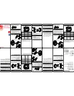
1. Installation key
2. Side marking
3. Recessed grip ring
4. Inside thumb-turn
Digital Locking Cylinder 3061
(Manual)
6. Installation instructions
25 / 54


