BA_ZV-ELIMATIC_DE-EN_11
www.simon-protec.com
Datum /
Date
: 12.08.2019
Ausgabe /
Issue
: 1.2 / 08.2019
Inbetriebnahme /
Commissioning
Seite /
Page
3
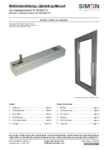
1.3 Produktbeschreibung
Der prozessorgesteuerte Verriegelungsantrieb ZV-ELIMATIC
wird in einem kompakten Metallgehäuse ausgeliefert.
Er beinhaltet einen Vierkantstift (7 x 7 mm) zur Anbindung an
den Verriegelungsmechanismus des Fensters und eine 6-Pol
Buchse zum Anschluss der zwei Dreier-Stecker (Ansteue-
rung / Zuleitung Antrieb).
Es bestehen Einstellmöglichkeiten über DIP-Schalter 1 – 2
(Drehrichtung / Drehwinkel).
Nach Ansteuerung in Richtung AUF (S = +24 V
DC
und
O = GND) dreht der Verriegelungsantrieb den per DIP-Schal-
ter eingestellten Öffnungswinkel in die entsprechende Rich-
tung. Nach Erreichen des Öffnungswinkels stoppt der Verrie-
gelungsantrieb, dann wird eine Pause von 2 Sekunden einge-
halten. Anschließend schaltet die interne Abschaltung die
24 V DC weiter zu den angeschlossenen Antrieben.
Nach Ansteuerung in ZU-Richtung (S = GND / O = +24 V DC)
werden zuerst die angeschlossen Antriebe in ZU angesteu-
ert. Nachdem über den angeschlossenen Folgekontakt „F“
die Endlagenbestätigung ZU vom Antrieb erfolgt ist, wird eine
Pausenzeit von 2 Sekunden abgewartet. Danach dreht der
Verriegelungsantrieb in Richtung ZU.
1.3 Product description
The processor-controlled locking device ZV-ELIMATIC is de-
livered in a compact metal housing.
It includes a square-pin (7 x 7 mm) for the connection to the
locking mechanisms of the window and a 6-pole connector for
two 3-pole plugs (supply / actuator connection).
Possible settings via DIP-switch 1 – 2 (rotary direction / angle
of rotation).
After triggering in direction OPEN (S
=
+24
V
DC
and
O = GND), the electric locking device turn the set opening an-
gle in the corresponding direction. When the OPEN position
is reached, a pause of 2 seconds is maintained. Then the in-
ternal cut-off switches the 24 V DC forward to the connected
actuators.
After triggering in direction CLOSE (S
=
GND
and
O = +24 V DC) the connected actuators are triggered in direc-
tion CLOSE. When the actuators have reached their
CLOSED position they forward this signal through the contact
“F”. The electric locking device maintain a pause time of
2 seconds. Then the electric locking device will start to turn
itself to CLOSE and lock the window.
2. Inbetriebnahme
Montageposition und Ausführung am Fenster festlegen.
Je nach Montageposition und Eigenschaften des Fens-
ters muss die Drehrichtung und / oder Drehwinkel (DIP-
Schalter) angepasst werden (siehe Kapitel 4. „Einstellun-
gen“ auf Seite 8), hierfür muss eine Reset-Fahrt durchge-
führt werden (siehe unten).
Für die Montage Variante A (innenliegende Verkabelung)
fertigen Sie eine Öffnung am Rahmen an (siehe Abbil-
dung 1: „Montagevariante A“ auf Seite 4).
Führen Sie die Anschlussleitungen (Ansteuerung Verrie-
gelung / Zuleitung Antrieb) durch die Leitungsdurchfüh-
rung des Fensterrahmens (Montagevariante A) oder
durch die Bohrungen des Deckels und sichern Sie diese
mit zwei Kabelbindern (siehe Abbildung 2: „Montagevari-
ante B“ auf Seite 5).
Klemmen Sie die Leitungen in die zwei mitgelieferten
Drei-Poligen Stecker ein (siehe Abbildung 5: „Elektri-
scher Anschluss“ auf Seite 7).
Setzen Sie, je nach Montagevariante, den entsprechen-
den Deckel in den Verriegelungsantrieb ein und ver-
schrauben sie diesen mit den beiden mitgelieferten
Schrauben.
Stecken Sie die Stecker in die Buchse auf der Platine im
Inneren des Antriebs.
Reset-Fahrt: Steuern Sie den noch nicht montierten Ver-
riegelungsantrieb in Richtung ZU an, bis er in seiner End-
lage abschaltet.
2. Commissioning
Determine the mounting position and option on the
window.
Depending on the mounting position an the characteris-
tics of the window, the rotary direction and / or the angle
of rotation must be adjusted (see chapter 4. “Settings” on
page 8).
For the mounting variant A (inside wiring) make a cut-out
of the frame (see Figure 1: “Mounting variant A” on
page 4).
Insert the connection cables (supply cable locking
device / feed actuator) through the cut-out of the window
frame (mounting variant A) or through the holes of the
cover and secure them with two cable ties (see Figure 2:
“Mounting variant B” on page 5).
Clamp the cables into the two supplied three-pin plugs
(see Figure 5: “Electrical connection” on page 7).
Depending on the mounting variant, insert the
corresponding cover into the locking drive and screw it
with the two supplied screws.
Plug in the plugs into the socket on the board inside of
the drive.
Reset-Drive: Trigger the not yet installed electric locking
device in direction CLOSE until it stops in its end
position.


