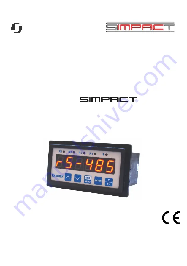
background image

SIMEX

®

USER MANUAL for

flow meter with pulse input 

   family:


type: 

SPI-94

firmware version: 

1.04 

or higher

Read the user's manual carefully before starting to use the unit. 

Producer reserves the right to implement changes without prior notice.

  22.10.2007


V.2.00  

Содержание SIMPACT SPI-94

Страница 1: ...meter with pulse input family type SPI 94 firmware version 1 04 or higher Read the user s manual carefully before starting to use the unit Producer reserves the right to implement changes without prio...

Страница 2: ...N 23 7 2 1 Numeric parameters digit change mode 23 7 2 2 Numeric parameters slide change mode 23 7 2 3 Switch parameters LIST type 24 7 3 MENU DESCRIPTION 24 7 3 1 rELAy1 menu 25 7 3 2 bEEP menu 27 7...

Страница 3: ...he application Incorrect configuration can cause defective operation which can lead to unit damage or an accident If in the case of a defect of unit operation there is a risk of a serious threat to th...

Страница 4: ...294967295 m3 with maximum resolution of 0 001 L Device can operate with different flow sensors acceptable flow factors of sensors from 0 01 to 10000 00 pulses per litre with resolution 0 01 pulses lit...

Страница 5: ...nt 0 2 or 4 NO 1A 250V AC cos 1 0 2 or 4 30mA 30VDC 100mW 24V 5 10 max 100 mA stabilized range max 0 24 mA load resistance max 700 current output is optional for two relays version only Instantaneous...

Страница 6: ...s tightening max torque 0 5 Nm Max connection leads diameter 2 5 mm2 Safety requirements according to PN EN 61010 1 installation category II pollution degree 2 voltage in relation to ground 300V AC in...

Страница 7: ...mmediately reported to the carrier Also write down the unit serial number on the housing and report the damage to the manufacturer Attached with the unit please find user s manual warranty assembly br...

Страница 8: ...1 Mounting hole dimensions Figure 4 2 Installing of brackets and dimensions of connectors Figure 4 3 Minimum distances when assembly of a number of units 8 1 mm max 5 mm 90 5 mm 43 mm 1 mm 8 mm 13 mm...

Страница 9: ...tions and laws In order to secure against accidental short circuit the connection cables must be terminated with appropriate insulated cable tips Tighten the clamping screws The recommended tightening...

Страница 10: ...of magnetically induced interference the use of twisted couples of signal cables so called spirals is recommended The spiral best if shielded must be used with RS 485 serial transmission connections I...

Страница 11: ...TIVE current output R2 n c n c Power supply depending on version n c COM pulse input n c total flow clearing Power supply depending on version 1 2 5 6 7 8 9 16 17 18 19 20 GND DATA DATA RS 485 Uo 24V...

Страница 12: ...g of inductive loads coils contactors power relays electromagnets motors etc it is required to use additional suppression circuit typically capacitor 47nF min 250VAC in series with 100R 5W resistor co...

Страница 13: ...re 4 9 Examples of suppression circuit connection a to relay terminals b to the inductive load Figure 4 10 Example of connection between flow counter and flow sensor with contactron output 13 N 3 4 3...

Страница 14: ...internal components and shorten the fault free time of unit operation In cases where the unit gets dirty do not clean with solvents For cleaning use warm water with small amount of detergent or in th...

Страница 15: ...Change of the present menu Modification of the parameter value Change of the display mode Symbol used in the manual FL Functions switching of the display between total and instantaneous measurements...

Страница 16: ...Ov is displayed in place of the result In that case parameters F unit Ftunit and F PrEc should be corrected to obtain proper result Total flow is displayed in units defined by parameter t unit L or m...

Страница 17: ...to see these digits press v button Most left decimal point signalizes additional more significant digits Press button to see these digits while most significant digits are displayed most right decima...

Страница 18: ...ure 6 2 If no peaks are detected while time timE elapses device starts to show the current value of input signal again The relays LEDs and the current output can be controlled depend on the current va...

Страница 19: ...6 3 the relay can be turned on modE on or off modE oFF when the input signal value is contained in zone A If two thresholds are used Figure 6 4 the relay will be turned on when value of input signal...

Страница 20: ...reshold hysteresis and threshold hysteresis respectively If t on and t oFF parameters are set to 0 then the relay state will be changed as soon as input value exceeds any of the border values see poin...

Страница 21: ...eters connected with relay outputs are described in paragraph rELAy1 menu 6 3 2 Two thresholds mode Description A B C D E points where measured signal exceeds border values expected value allowed devi...

Страница 22: ...ttings The meaning of the particular parameters is described in paragraph MENU DESCRIPTION Some of the parameters can be accessed without menu entering quick view mode If current flow is displayed LED...

Страница 23: ...t In mode by digit Edit dig pressing one of the keys or v causes change of current position flashing digit or the sign Short pressing of the ENTER button causes change of the position digit Press ENTE...

Страница 24: ...ge of current flashing digit slide change of value acceleration deceleration direction change While editing switch parameter selection of switch parameter If numerical parameter is being edited a shor...

Страница 25: ...Et P first threshold of the relay range 0 999999 Threshold is the medium value of relay hysteresis SEt P2 second threshold of the relay range 0 999999 This threshold is accessible when modE parameter...

Страница 26: ...olds the lower threshold means lower one of SEt P and SEt P2 thresholds Out two threshold mode relay is turned OFF when the input value is bigger than bigger threshold HYSt and lower than lower thresh...

Страница 27: ...than mbtimE parameter see description rS 485 menu 7 3 2 bEEP menu This menu contains options connected with acoustic signal AL if this parameter is set to on any critical situation causes by acoustic...

Страница 28: ...33 s 33 66 Tab 7 1 Allowable settings of FrEq parameter and related with them minimum durations of logical states ZEro t maximum delay time of successive revolution This parameter is defined with 0 1...

Страница 29: ...nit and t unit are conventional and can be exchanged to any other pair of units e g for powders it can be kilogram and tonne Ftunit time unit used for flow rate displaying It can be set to SEC seconds...

Страница 30: ...s 7 3 6 Init d parameter This Parameter defines type of the value displayed after power on the meter It is possible to set it to Flo current flow rate instantaneous flow tot lowest part of total flow...

Страница 31: ...o total flow counter result OUt LO this parameter determines the input value for which the output current is minimal 0 mA or 4 mA depend of current output mode Outmod OUt HI this parameter determines...

Страница 32: ...om 0 to 99 9 Parameter Hi r defines lower border of the range due to formula Imax 20 mA 20 mA Hi r This parameter can be set from 0 to 19 9 In example on page 38 of the DISPLAY VALUES CALCULATION para...

Страница 33: ...rrent value HOLd relay LED operates depend on the peak drop value HOUt current output operation mode rEAL current output operates depend on the current value HOLd current output operates depend on the...

Страница 34: ...ater than the value of mbtimE parameter the relays and the current output which are controlled via RS 485 interface will set to alert state see OUtPUt menu and rELAy1 menu description Parameter mbtimE...

Страница 35: ...lows to restore the factory settings of the device To get the access to this option special password is required 5465 next the device displays acknowledge question SEt Press ENTER to acknowledge the r...

Страница 36: ...SC bEEP MENU ESC inPUt MENU ESC AL r1 r2 r3 r4 Parameter edition ENTER MENU ESC ENTER ENTER MENU ESC PULSEL Freq ZEro t mEAS t Parameter edition ENTER MENU ESC ENTER ENTER MENU ESC vALUE SEt P2 HYSt m...

Страница 37: ...tcod Acc r1 Acc r2 Acc r3 Acc r4 ENTER MENU ESC ENTER ENTER MENU ESC modE PEA timE H dis H r1 H r2 H r3 H r4 Parameter edition HOUt See previous page MENU ESC SEt 4 digit special password entering 0 _...

Страница 38: ...parameters 1 start bit 8 data bits 1 or 2 stop bit 2 bits are send 1 and 2 bits are accepted when receive no parity control Baud rate selectable from 1200 to 115200 bits second Transmission protocol...

Страница 39: ...9 Total flow counter result quantity of l 0Ch1 No 0 999 Total flow counter result quantity of ml 10h Yes 0 10 FrEq parameter in inPUt menu input filter 0 10Hz 1 15Hz 2 20Hz 3 30Hz 4 40Hz 5 50Hz 6 100H...

Страница 40: ...meter bit 2 Acc r3 parameter bit 4 Acc r4 parameter 25h Yes 0 5 rESP parameter in rS 485 menu additional response delay 0 no additional delay 1 10c option 2 20c option 3 50c option 4 100c option 5 200...

Страница 41: ...hile relay is controlled due to total flow counter value 0 lit 1 m3 Parameters or relay R2 operation 40h 41h Yes Yes 0 999999 SEt P parameter in rELAy2 menu no decimal point included 42h 43h Yes Yes 0...

Страница 42: ...1 on 2 off 59h 5Ah Yes Yes 0 999999 SEt P2 parameter in rELAy2 menu no decimal point included 5Bh Yes 0 1 vALUE parameter in rELAy3 menu kind of value controlled relay 0 FLo 1 tot 5Ch Yes 0 3 t PrEc...

Страница 43: ...OLd menu maximum peaks or drops display time expressed in seconds 73h Yes 0 1 HdiS parameter in HOLd menu the type of values displayed on the display 0 current measurement value 1 peaks or drops value...

Страница 44: ...0 1 t unit parameter in OUtPUt menu the unit of OUt LO and OUt HI parameters displaying while active current output is controlled due to total flow counter value 0 lit 1 m3 1 it is recommended to rea...

Страница 45: ...s the device address 01h ADDR FUNC REG H L COUNT H L CRC L H 01 03 00 01 00 03 54 0B The answer ADDR FUNC BYTE C DATA H1 L1 DATA H2 L2 DATA H3 L3 CRC L H 01 03 06 00 01 86 A0 00 00 2A B4 DATA H1 L1 re...

Страница 46: ...o the net BROADCAST message ADDR FUNC REG H L COUNT H L CRC L H 00 06 00 22 00 04 29 D2 DATA H 0 DATA L 4 new baud rate 19200 baud Device do not reply to BROADCAST type messages 5 Try to write imprope...

Страница 47: ...unit Unit of t on toFF parameters of relay SEC 27 ALArmS Reaction for critical situation of relay oFF 27 Parameters of relay R2 operation rELAy2 menu vALUE Kind of value controlled relay state FLo 25...

Страница 48: ...d 80 0 25 SEt P2 Relay second threshold 90 0 25 HYSt Hysteresis of relay 0 0 25 t PrEc Precision of thresholds and hysteresis displaying while relay is controlled due to total flow counter value 0 25...

Страница 49: ...on configuration Init d Kind of value displayed after device power on FLo 30 Configuration of data filtration FiLtEr menu vALUE Filtering ratio 0 30 droP Measured value change causing of temporal filt...

Страница 50: ...33 Settings of access to the configuration parameters SECU menu Acc r1 Permission to changes of relay R1 threshold without of the user password knowledge on 33 Acc r2 Permission to changes of relay R...

Страница 51: ...User manual for flow meter with pulse input SPI 94 51...

Страница 52: ...SIMEX SIMEX Sp z o o ul Wielopole 7 PL 80 556 Gda sk Poland tel 48 58 762 07 77 fax 48 58 762 07 70 http www simex com pl e mail info simex com pl...

Отзывы: