

Safety 2
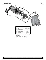
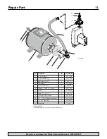
For parts or assistance, call Simer Customer Service at 1-800-468-7867
Important Safety Instructions
SAVE THESE INSTRUCTIONS - This manual contains
important instructions that should be followed during
installation, operation, and maintenance of the product.
Save this manual for future reference.
This is the safety alert symbol. When you see this
symbol on your pump or in this manual, look for one of
the following signal words and be alert to the potential
for personal injury!
indicates a hazard which, if not avoided, will
result in death or serious injury.
indicates a hazard which, if not avoided,
could result in death or serious injury.
indicates a hazard which, if not avoided,
could result in minor or moderate injury.
NOTICE addresses practices not related to personal injury.
Carefully read and follow all safety instructions in this
manual and on pump .
Keep safety labels in good condition.
Replace missing or damaged safety labels.
Electrical Safety
Capacitor voltage may be hazardous .
To discharge motor capacitor, hold insulated handle
screwdriver BY THE HANDLE and short capacitor
terminals together. Do not touch metal screwdriver blade
or capacitor terminals. If in doubt, consult a qualified
electrician.
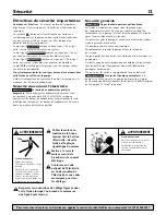
General Safety
Do not touch an operating motor. Modern
motors are designed to operate at high temperatures. To
avoid burns when servicing pump, allow it to cool for
20 minutes after shut-down before handling.
Do not allow pump or any system component to freeze.
To do so will void warranty.
Pump water only with this pump.
Periodically inspect pump and system components.
Wear safety glasses at all times when working on pumps.
Keep work area clean, uncluttered and properly lighted;
store properly all unused tools and equipment.
Keep visitors at a safe distance from the work areas.
Pump body may explode if used as a
booster pump unless relief valve capable of passing full
pump flow at 75 psi is installed.
WARNING
Hazardous pressure!
Install pressure relief valve in
discharge pipe.
Release all pressure on
system before working on
any component.
WARNING
Hazardous voltage .
Can shock, burn, or
cause death.
Ground pump before
connecting to power supply.
Disconnect power before
working on pump, motor
or tank.
Wire motor for correct
voltage . See “Electrical”
section of this manual
and motor nameplate .
Ground motor before
connecting to
power supply .
Meet National Electrical
Code, Canadian
Electrical Code, and
local codes for
all wiring .
Follow wiring
instructions in this
manual when
connecting motor to
power lines .
Содержание 2806E
Страница 32: ......


