61
EN
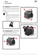
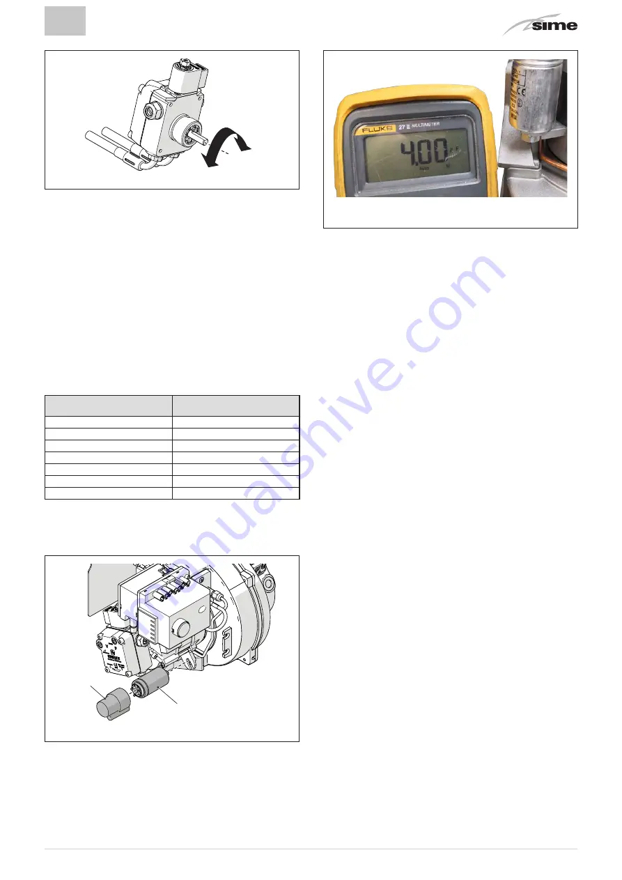
Fig. 51
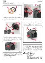
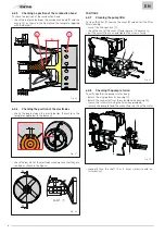
Replace the pump if remains seized or if it resists manual ro-
tation.
To mount the pump back on:
– apply the joint to the pump shaft (4) and insert it in the motor
housing;
– screw the oil pipe onto the housing (1);
– put the connector back onto the solenoid valve housing (2).
a
WARNING
When the burner starts up, check that there are no
leakages from the pump.
6.2.9
Scheduled replacement of worn components
The table below shows the components subject to wear and
their life cycle, at the end of which they should be replaced
exclusively by the
SIME
Technical Service or by professionally
qualified personnel
Components
Life cycle
(years)
Nozzles
1
Seals
2
Fuel supply pipes
2
Flame monitoring systems
3
Ignition electrodes
2
Power cable
5
Magnesium anode
1
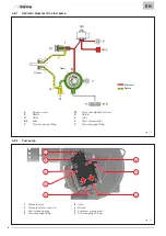
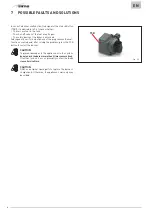
6.2.10 Replacing the capacitor
To replace the capacitor:
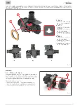
– remove the protective cap (1) from the capacitor (2);
1
2
Fig. 52
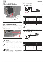
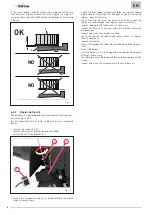
– disconnect the power supply to the capacitor;
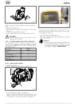
– connect a tester to the Faston terminals of the capacitor; if the
reading is roughly 10% higher than the rated capacity shown
on the capacitor, it means that the capacitor is damaged.
Fig. 53
The value shown in the figure refers to a 4 μF capacitor and is
purely indicative. Please refer to the characteristics of the capa-
citor mounted on the burner.
– Remove the capacitor (2) and replace it
– Mount the components back on by performing the above
steps in reverse order.
m
CAUTION
– After completing the maintenance operations and
mounting the burner back onto the boiler, the bur-
ner must be started up by performing the procedure
described in the chapter “COMMISSIONING”.
Содержание FUEL EV
Страница 98: ...98 ...
Страница 99: ...99 ...
Страница 100: ...Fonderie Sime S p A Via Garbo 27 37045 Legnago Vr Tel 39 0442 631111 Fax 39 0442 631292 www sime it ...

