background image

135

ROSSO - RED

NERO - BL

AC

K

MARRONE - BR

OW

N

NERO - BL

AC

K

MARRONE - BR

OW

N

BLU - BL

UE

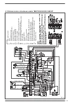
2.7.2 Schema electrica de functionare modelele “DUETTO 20-30-40 OF/30-40 BF”

Fig. 9/a

LEGENDA

IG

Intrerupator 

general

R

Releu

TM 

Termostat 

de 

minima

TL

Termostat 

de 

limita 

incalzire

VP

Supapa 

presostatica

TS

Termostat 

de 

siguranta

E/I

Intrerupator 

vara/iarna

TC

Termostat 

de 

cazan

SPA

Led 

de 

semnalizare 

interventie 

presostat 

apa 

SA

Led 

de 

semnalizare 

prezenta 

tensiune 

SB

Lampa 

de 

semnalizare 

ce 

indica 

blocarea 

arzator

PA

Presostat 

apa 

P

Pompa 

instalatie 

B

A

rzator

TA

Termostat 

de 

ambianta

VD

Vana 

deviatoare

C

Conectori 

regulator 

RVA 

43.222 

(optional)

SS

Sonda 

imersie 

boiler 

QAZ21(optional)

SC

Sonda 

imersie 

cazan 

QAZ21(optional)

SE

Sonda 

temperatura 

exterioara 

QAC31(optional)

UA

Dispozitiv 

de 

ambianta 

QAA70 

(optional)

OP

Programator 

timp

NOTE:

Pentru 

conectarea 

termostatului 

de 

ambianta 

(TA)

scoateti 

puntea 

dintre 

bornele 

7-8.

Pentru 

conectarea 

regulatorului 

 RVA 

43.222 

scoateti

puntea 

dintre 

bornele 

7-8 

si 

17-18.

Pentru 

conectarea 

programator 

timp

(OP) 

scoateti 

pun-

tea 

dintre 

bornele 

6-7.

Содержание DUETTO 20 OF

Страница 1: ...Solo Duetto OF BF IT ES PT GB FR BE RO CERTIFICAZIONE DEL SISTEMA DI QUALITA AZIENDALE ...

Страница 2: ...are che non vi siano liquidi o materiali infiammabili nelle immediate vicinanze della caldaia Accertarsi che il collegamento elettrico sia stato effettuato in modo corretto e che il filo di terra sia collegato ad un buon impianto di terra Verificare che il condotto di evacuazione dei prodotti della combustione sia libero Accertarsi che le eventuali saracinesche siano aperte Assicurarsi che l impia...

Страница 3: ...iatore a combustione stagna Atte nersi alle istruzioni riportate in questo manuale per una corretta installazione e un perfetto funzionamento dell appa recchio 1 1 DESCRIZIONE DELL APPARECCHIO 1 2 DIMENSIONI Fig 1 SOLO 20 OF SOLO 30 40 OF BF DUETTO 20 30 40 OF 30 40 BF P Profondità 650 750 30 OF BF 850 40 OF BF 650 20 OF 750 30 OF BF 850 40 OF BF M Mandata impianto G 1 UNI ISO 228 1 G 1 UNI ISO 22...

Страница 4: ... 42 9 52 8 46 3 CO2 12 5 12 5 12 5 Temperatura max esercizio C 95 95 95 Potenza elettrica assorbita OF BF W 220 200 230 180 210 Campo regolazione riscaldamento C 45 85 45 85 45 85 Produzione acqua sanitaria Portata sanitaria specifica EN625 l min Portata sanitaria continua t 30 C l h Portata sanitaria minima l min Pressione max esercizio bollitore bar Bruciatore gasolio Ugello bruciatore 0 50 0 60...

Страница 5: ...nza elettrica assorbita OF BF W 220 205 235 185 215 Campo regolazione riscaldamento C 45 85 45 85 45 85 Produzione acqua sanitaria Portata sanitaria specifica EN625 l min 9 7 8 7 12 5 11 0 14 8 14 2 Portata sanitaria continua t 30 C l h 670 590 890 780 1 000 1 000 Portata sanitaria minima l min 2 5 2 5 2 5 Pressione max esercizio bollitore bar 6 6 6 Bruciatore gasolio Ugello bruciatore 0 60 60 W 0...

Страница 6: ... Guaina porta sonde 3 Pannello comandi 4 Riempimento 5 Pressostato acqua 6 Idrometro 7 Circolatore impianto 8 Aspirazione aria bruciatore stagno versione BF LEGENDA 1 Bruciatore gasolio 2 Guaina porta sonde 3 Pannello comandi 4 Bollitore istantaneo 5 Riempimento 6 Valvola deviatrice 3 vie 7 Pressostato acqua 8 Idrometro 9 Circolatore impianto 10 Aspirazione aria bruciatore stagno versione BF ...

Страница 7: ...spansione 6 Bruciatore gasolio 7 Circolatore impianto 8 Idrometro 9 Rubinetto scarico caldaia 10 Pressostato acqua LEGENDA 1 Corpo caldaia 2 Riempimento 3 Valvola sicurezza caldaia 4 Valvola sfiato automatica 5 Vaso espansione 6 Bruciatore gasolio 7 Circolatore impianto 8 Idrometro 9 Rubinetto scarico caldaia 10 Pressostato acqua impianto 11 Pressostato acqua sanitario 12 Bollitore istantaneo 13 V...

Страница 8: ...la richiesta di acqua calda sanitaria parte istantaneamente il pressostato che commuta la valvola deviatrice con sentendo l utilizzo pressoché immedia to dell acqua calda Per regolare la portata acqua sanita ria agire sul regolatore di portata del pressostato acqua fig 5 Avvitando in senso orario il regolato re si riduce la portata di prelievo acqua sanitaria aumentando di con seguenza la relativa...

Страница 9: ...ni singolo accessorio da utilizzare nella configurazione di scarico è riportata in Tabella A Utilizzare esclusivamente accessori originali SIME e assicurarsi che il colle gamento avvenga in maniera corretta così come indicato dalle istruzioni for nite a corredo degli accessori 2 3 3 Scarico fumi con condotti separati ø 80 Le caldaie versione SOLO 30 BF DUETTO 30 BF sono predisposte per il collegam...

Страница 10: ...4 2 2 2 2 3 10 2 5 6 min 700 max 16 m equivalenti max 16 m equivalenti max 7 6 m verticali 8 9 Fig 6 a LEGENDA 1 Terminale di scarico cod 8089501 2 a Prolunga in acciaio inox L 1000 2 b Prolunga in acciaio inox L 500 3 a Curva a 90 in acciaio inox 3 b Curva a 45 in acciaio inox 4 Recupero condensa verticale in acciaio inox L 148 5 Tegola con snodo cod 8091300 6 Terminale uscita a tetto 7 Kit di sc...

Страница 11: ...punto 1 3 che sono riferiti alla pressio ne atmosferica al livello del mare Nel caso che l impianto richieda regola zioni diverse da quelle di fabbrica que ste possono essere eseguite solo da personale autorizzato seguendo le istruzioni sotto riportate per accedere agli organi di regolazione dell unità di combustione rimuovere la porta del mantello di caldaia 2 5 1 Regolazione serranda aria Per ef...

Страница 12: ...i funzio namento ha inizio prima che il combu stibile abbia raggiunto la temperatura ottimale Alla successiva ripartenza sarà trascorso quel tempo 2 3 minuti sufficiente per creare le condizioni ideali di avviamento Il gruppo riscaldatore non è montato sulle versioni SOLO 40 OF BF DUETTO 40 OF BF in quanto non necessario 2 7 ALLACCIAMENTO ELETTRICO La caldaia è corredata di cavo elettri co di alim...

Страница 13: ...ruciatore TA Termostato ambiente C Connettori centralina RVA 43 222 optional SS Sonda immersione bollitore QAZ21 optional SC Sonda immersione caldaia QAZ21 optional SE Sonda temperatura esterna QAC31 optional UA Unità ambiente QAA70 optional PB Pompa bollitore OP Orologio programmatore NOTE Collegando il termostato ambiente TA togliere il ponte tra i morsetti 4 5 Collegando la centralina RVA 43 22...

Страница 14: ...ne SB Spia blocco bruciatore PA Pressostato acqua P Pompa impianto B Bruciatore TA Termostato ambiente VD Valvola deviatrice C Connettori centralina RVA 43 222 optional SS Sonda immersione bollitore QAZ21 optional SC Sonda immersione caldaia QAZ21 optional SE Sonda temperatura esterna QAC31 optional UA Unità ambiente QAA70 optional OP Orologio programmatore NOTE Collegando il termostato ambiente T...

Страница 15: ... Valvola gasolio Fiamma Lampada blocco Normale Blocco dovuto a mancanza di accensione NOTA Nelle versioni DUETTO 30 OF BF prive di termostato il riscaldatore in inverno è sempre attivo 5 s 12 s 12 s Consenso avviamento Motore Trasform accensione Valvola gasolio Fiamma Lampada blocco 2 7 4 Diagramma di funzionamento SOLO 40 OF BF DUETTO 40 OF BF Normale Blocco dovuto a mancanza di accensione ...

Страница 16: ...2 fino a bloccarla a metà corsa In questo modo rimangono parzial mente aperte entrambe le uscite riscaldamento e sanitario 3 1 DIMENSIONI CAMERA COMBUSTIONE La camera combustione è del tipo a passaggio diretto ed è conforme alla norma EN 303 3 allegato E Le dimensioni sono riportate in fig 10 Un apposito pannello di protezione è applicato sulla parete interna della testata posteriore di tutti i mo...

Страница 17: ...uovere il guscio destro bloccato da quattro viti prestando attenzione a non rovinare le guarni zioni di tenuta OR Per lo smontaggio del portaspruzzo e del gruppo riscaldatore agire nel seguente modo aprire il coperchio dell apparec chiatura bloccato da una vite staccare i cavi del riscaldatore 1 fig 15 a protetti dalla guaina ter moresitente e farli passare attra verso il foro dopo aver tolto il r...

Страница 18: ...gio del suppor to elica e rimuovere lo stesso Spazzolare delicatamente l elica disco di turbolenza Pulire accuratamente gli elettrodi di accensione Pulire accuratamente la fotoresi stenza da eventuali depositi di sporci zia depositatesi sulla sua superficie Pulire i restanti componenti della testa di combustione da eventuali depositi Ad operazioni ultimate rimontare il tutto con procedimento inver...

Страница 19: ...ensione ed il fun zionamento dell apparecchiatura del bruciatore Il bruciatore si accende regolarmen te ma si spegne subito dopo Controllare il rilevamento fiamma la taratura aria ed il funzionamento dell apparecchiatura Difficoltà di regolazione del bruciato re e o mancanza di rendimento Controllare il regolare afflusso di combustibile la pulizia del generatore il non intasamento del condotto sca...

Страница 20: ...a di lavoro di 60 C fig 21 TERMOSTATO SICUREZZA Il termostato di sicurezza a riarmo ma nuale interviene provocando l imme diato spegnimento del bruciatore quando la temperatura supera i 110 C Per riattivare l apparecchio svitare il cappuccio di protezione e premere il ISTRUZIONI PER L UTENTE AVVERTENZE In caso di guasto e o cattivo funzionamento dell apparecchio disattivarlo astenendosi da qualsia...

Страница 21: ...gnere la caldaia è sufficiente premere il tasto dell interruttore gene rale fig 19 Chiudere i rubinetti del combustibile e dell acqua dell impianto termico se il generatore rimarrà inuti lizzato per un lungo periodo RIEMPIMENTO IMPIANTO Verificare periodicamente che l idro metro abbia valori di pressione ad impianto freddo compresi tra 1 1 2 bar Nel caso si accenda la spia aran cio per intervento ...

Страница 22: ... conservare la propria copia da esibire al Centro Assistenza Autorizzato in caso di necessità oppure nel caso non sia stata effettuata la verifica iniziale dovrà esi bire la documentazione fiscale rilasciata all acquisto dell ap parecchio Per le caldaie a gasolio esclusi i gruppi termici e scaldaba gni gas non è prevista la verifica iniziale gratuita L Utente per rendere operante la garanzia dovrà...

Страница 23: ...718 MANTOVA Mantova Ravanini Marco 0376 390547 Castigl Stiviere Andreasi Bassi Guido 0376 672554 Castigl Stiviere S O S Casa 0376 638486 Commessaggio Somenzi Mirco 0376 98251 Felonica Po Romanini Loris 0386 916055 Gazoldo degli Ippoliti Franzoni Bruno 0376 657727 Guidizzolo Gottardi Marco 0376 819268 Marmirolo Clima World 0376 460323 Poggio Rusco Zapparoli William 0386 51457 Porto Mantovano Clima ...

Страница 24: ...o A M Clementi 0722 330628 ABRUZZO MOLISE L AQUILA Avezzano Massaro Antonello 0863 416070 Carsoli Proietti Vittorio 0863 995381 Cesaproba Cordeschi Berardino 0862 908182 Cese di Preturo Maurizi Alessio 0862 461866 Pratola Peligna Giovannucci Marcello 0864 272449 CAMPOBASSO Termoli G S D di Girotti 0875 702244 Campobasso Catelli Pasqualino 0874 64468 CHIETI Chieti Almagas 085 810938 Fara S Martino ...

Страница 25: ...atas cercanías de la caldera Asegurarse que la conexión eléctrica haya sido efectuada en modo correcto y que el cable a tierra esté conectado a una buena instalación de tierra Controlar que el conducto de evacuación de los productos de la combustión esté libre Asegurarse que las eventuales válvulas estén abiertas Asegurarse que la instalación haya sido cargada con agua y resulte bien ventilada Con...

Страница 26: ... son calderas con quemador de combustión estanca Seguir las instrucciones incluidas en este manual para una correcta insta lación y un perfecto funcionamiento del aparato 1 DESCRIPCION DE LA CALDERA 1 2 DIMENSIONES SOLO 20 OF SOLO 30 40 OF BF DUETTO 20 30 40 OF 30 40BF P Profundidad 650 750 30 OF BF 850 40 OF BF 650 20 OF 750 30 OF BF 850 40 OF BF M Ida instalación G 1 UNI ISO 228 1 G 1 UNI ISO 22...

Страница 27: ...9 42 9 52 8 46 3 CO2 12 5 12 5 12 5 Temperatura máxima de servicio C 95 95 95 Potencia eléctrica absorbida OF BF W 220 200 230 180 210 Campo de regulación calefacción C 45 85 45 85 45 85 Producción agua sanitaria Caudal sanitario específico EN625 l min Caudal sanitario continuo t 30 C l h Caudal sanitario mínimo l min Presión máxima de servicio hervidor bar Quemador de gasoil Inyector quemador 0 5...

Страница 28: ...eléctrica absorbida OF BF W 220 205 235 185 215 Campo de regulación calefacción C 45 85 45 85 45 85 Producción agua sanitaria Caudal sanitario específico EN625 l min 9 7 8 7 12 5 11 0 14 8 14 2 Caudal sanitario continuo t 30 C l h 670 590 890 780 1 000 1 000 Caudal sanitario mínimo l min 2 5 2 5 2 5 Presión máxima de servicio hervidor bar 6 6 6 Quemador de gasoil Inyector quemador 0 60 60 W 0 75 6...

Страница 29: ... de alojamiento bulbos 3 Panel de mandos 4 Rellenado 5 Presóstato agua 6 Hidrómetro 7 Bomba instalación 8 Aspiración aire del quemador estanco versión BF LEYENDA 1 Quemador de gasoil 2 Vaina de alojamiento bulbos 3 Panel de mandos 4 Hervidor instantáneo 5 Rellenado 6 Válvula de derivación de 3 vías 7 Presóstato agua 8 Hidrómetro 9 Bomba instalación 10 Aspiración aire del quemador estanco versión B...

Страница 30: ... de expansión 6 Quemador de gasoil 7 Bomba instalación 8 Hidrómetro 9 Grifo descarga caldera 10 Presóstato agua LEYENDA 1 Cuerpo caldera 2 Rellenado 3 Válvula de seguridad 4 Válvula purga automática 5 Vaso de expansión 6 Quemador de gasoil 7 Bomba instalación 8 Hidrómetro 9 Grifo descarga caldera 10 Presóstato agua instalación 11 Presóstato agua sanitario 12 Hervidor instantáneo 13 Válvula de deri...

Страница 31: ...ador se aumenta el caudal de retiro de agua sanitaria disminuyen do en consecuencia la temperatura respectiva 2 2 3 Características agua de alimentación Para prevenir incrustaciones calcá reas y averías en el intercambiador sanitario el agua de alimentación no tiene que presentar una dureza supe rior a los 20 F Siempre es oportuno verificar las características del agua utilizada e instalar equipos...

Страница 32: ...carga está reportada en la Tabla A Utilice exclusivamente accesorios ori ginales SIME y asegúrese que la conexión se produzca en modo cor recto así como se indica en las instrucciones suministradas junto a los accesorios 2 3 3 Descarga de humos con conductos separados ø 80 Las calderas versión SOLO 30 BF DUETTO 30 BF están preparadas para conectarse a conductos sepa 30 P S K H 1 2 3 4 2 5 6 7 7 3 ...

Страница 33: ...gitud del conducto de aspiración no debe superar los 16 metros equivalentes La longitud del conducto de descarga no debe superar los 6 metros equivalentes En las salidas de techo con descarga siempre debe haber una recuperación de la condensación 4 la longitud vertical del conducto sin cambios de dirección no debe superar los 7 6 metros LEYENDA 1 Terminal de descarga cód 8089501 2 a Alargador en a...

Страница 34: ...l caso que la instalación requiera regulaciones diversas de aquellas rea lizadas en la fábrica estas pueden ser realizadas sólo por personal autoriza do siguiendo las instrucciones debajo reportadas para acceder a los órga nos de regulación de la unidad de com bustión quitar la puerta de la envolven te 2 5 1 Regulación cierre de aire Para efectuar la regulación de la com puerta de aire accionar el...

Страница 35: ...cionamiento inicia antes que el combustible haya alcanza do la temperatura óptima En las pue stas en marcha sucesivas transcurrirá un tiempo 2 3 minutos que será sufi ciente para crear las condiciones idea les de puesta en marcha El grupo calefactor no está montado en las versiones SOLO 40 OF BF DUETTO 40 OF BF ya que no es necesario 2 7 CONEXION ELECTRICA La caldera está suministrada con cable el...

Страница 36: ...omba instalación B Quemador TA Termostato ambiente C Conectores centralita RVA 43 222 opcional SS Sonda de inmersión hervidor QAZ21 opcional SC Sonda de inmersión caldera QAZ21 opcional SE Sonda de temperatura exterior QAC31 opcional UA Unidad ambiente QAA70 opcional PB Bomba hervidor OP Reloj programador NOTAS Conectando el termostato ambiente TA quite el puente entre los bornes 4 5 Conectando la...

Страница 37: ... debido a la falta de encendido Fig 9 a LEYENDA IG Interruptor general R Relé TM Termostato de mínima TL Termostato límite VP Válvula presostática TS Termostato de seguridad E I Interruptor Ver Inv TC Termostato caldera SPA Luz indicadora intervención presostato agua SA Luz indicadora presencia tension SB Luz indicadora bloqueo quemador PA Presóstato agua P Bomba instalación B Quemador TA Termosta...

Страница 38: ...carrera En este modo quedan parcialmente abiertas ambas salidas calefacción y sanitaria 3 1 DIMENSIONES CAMARA DE COMBUSTION La cámara de combustión es del tipo de pasaje directo y está en conformi dad a la norma EN 303 3 anexo E Las dimensiones están enunciadas en la fig 10 Un respectivo tablero de pro tección está aplicado sobre la pared interior del cabezal posterior de todos los modelos 3 2 AL...

Страница 39: ...llos laterales y quite la envolvente derecha blo queada por cuatro tornillos prestan do atención a no arruinar las juntas de retención OR Para el desmontaje del portapulveri zador y del grupo calefactor actúe del siguiente modo abra la tapa del equipo bloqueada por un tornillo desconecte los cables del calefactor 1 fig 15 a protegidos por la funda termore sistente y hágalos pasar a través del orif...

Страница 40: ...ón del soporte de hélice y remover el mismo Cepillar delicadamente la hélice disco de turbulencia Limpiar cuidadosamente los electro dos de encendido Limpiar cuidadosamente la fotore sistencia de eventuales depósitos de suciedad depositados sobre la superficie Limpiar los restantes componentes del cabezal de combustión de even tuales depósitos Una vez terminadas las operaciones monte nuevamente to...

Страница 41: ...ón de chispas de encendido y el funciona miento del equipo del quemador El quemador se enciende regular mente pero después se apaga Controle el relevamiento llama la calibración aire y el funcionamiento del equipo Dificultad de regulación del quema dor y o falta de rendimiento Controle el regular flujo de combus tible la limpieza del generador la no obstrucción del conducto de descar ga de humos l...

Страница 42: ... SEGURIDAD El termostato de seguridad de mando manual interviene cuando la tempera tura supera los 110 C provocando el apagado inmediato del quemador Para reactivar el equipo destornillar el capu chón de protección y presionar el pul sador que se encuentra debajo fig 21 Si el fenómeno se verifica frecuente mente se debe requerir la interven ción del personal técnico autorizado para un control INST...

Страница 43: ...ador quedará inutilizado por un período largo RELLENADO DE LA INSTALACION Verifique periódicamente que el hidró metro tenga valores de presión con la instalación en frío comprendidos entre 1 1 2 bar En el caso que se encienda la luz indicadora anaranjada por inter vención del presóstato de agua blo queando el funcionamiento del quema dor restablecer la presión girando el grifo de carga en sentido ...

Страница 44: ...42 ...

Страница 45: ...ateriais inflamáveis prossimos a caldeira Acertar se que a ligação elétrica seja feita in modo correto e que o fio terra seja ligado a uma boa ligação de terra Verificar que o tubo de evacuação dos produtos de combustão sejam livres Verificar que as eventuais portas de ferro sejam abertas Certificar se que a instalaçào seja cheia de água e resulte esbaforida Verificar que o circulador não resulte ...

Страница 46: ...m queimador a combustão estanque As instruções constantes neste manual devem ser seguidas para uma instalação correcta e um perfeito funcionamento do aparelho 1 DESCRIÇÕES DO APARELHO 1 2 DIMENÇÕES Fig 1 SOLO 20 OF SOLO 30 40 OF BF DUETTO 20 30 40 OF 30 40 BF P Profondidade 650 750 30 OF BF 850 40 OF BF 650 20 OF 750 30 OF BF 850 40 OF BF M Passada ao circuito G 1 UNI ISO 228 1 G 1 UNI ISO 228 1 G...

Страница 47: ... 35 9 42 9 52 8 46 3 CO2 12 5 12 5 12 5 Temperatura max funcionamento C 95 95 95 Potência elétrica assorbida OF BF W 220 200 230 180 210 Campo de regolazione aquecimento C 45 85 45 85 45 85 Produção de água sanitaria Carga sanitario especifico EN 625 l min Carga sanitario continuo t 30 C l h Carga sanitario minimo l min Pressão max de exercicio dos fervidores bar Queimadores de combustivel Injetor...

Страница 48: ...ncia elétrica assorbida OF BF W 220 205 235 185 215 Campo de regolazione aquecimento C 45 85 45 85 45 85 Produção de água sanitaria Carga sanitario especifico EN 625 l min 9 7 8 7 12 5 11 0 14 8 14 2 Carga sanitario continuo t 30 C l h 670 590 890 780 1 000 1 000 Carga sanitario minimo l min 2 5 2 5 2 5 Pressão max de exercicio dos fervidores bar 6 6 6 Queimadores de combustivel Injetor dos queima...

Страница 49: ...dos sensores 3 Painel de controle 4 Enchimento 5 Pressostato água 6 Hidrometro 7 Circolador do implanto 8 Aspiração do ar do queimador estanque versão BF LEGENDA 1 Queimador de combustivel 2 Bainha de alojamento dos sensores 3 Painel de controle 4 Fervidor instantâneo 5 Enchimento 6 Valvola desviadora tres vias 7 Pressostato água 8 Hidrometro 9 Circolador do implanto 10 Aspiração do ar do queimado...

Страница 50: ...or de combustivel 7 Circulador do implanto 8 Hidrometro 9 Torneira de descarga da caldeira 10 Pressòstato água LEGENDA 1 Corpo da caldeira 2 Enchimento 3 Valvula de segurança da caldeira 4 Valvula de esfogo automatica 5 Vaso espansão 6 Queimador de combustivel 7 Circulador do implanto 8 Hidrometro 9 Torneira de descarga da caldeira 10 Pressòstato água do implanto 11 Pressòstato água sanitaria 12 A...

Страница 51: ...umo de água quente sanitá ria este é detectado pelo pressostato que faz comutar a válvula desviadora permitindo disponibilizar imediatamen te a água quente Para regular o caudal de água sanitá ria actuar no regulador de caudal do pressóstato da água fig 5 Girando no sentido dos ponteiros do relógio o regulador reduz o caudal de admissão de água sanitária aumentando consequentemente a sua temperatu...

Страница 52: ...cessório a utilizar na configu ração de evacuação estão indica das na Tabela A Utilizar exclusivamente acessórios de origem SIME e certificar se que a ligação seja efectuada correctamente como indicado nas instruções forneci das com os acessórios 2 3 3 Saída de fumos com condutas separadas ø 80 As caldeiras versão SOLO 30 BF DUETTO 30 BF estão predispostas para a ligação a condutas separadas em aç...

Страница 53: ...6 m verticali 8 9 Fig 6 a TABELA B ATENÇÃO O comprimento máximo da conduta de aspiração não deverá ser superior a 16 metros equivalentes O comprimento máximo da conduta de descarga não deverá ser superior a 6 metros equivalentes Nas saídas pelo tecto utilizar sempre a recuperação da condensação 4 e o comprimento máximo vertical da conduta sem mudanças de direcção não deverá ser superior a 7 6 metr...

Страница 54: ...o equipamento necessite de regulação diferente daquela de fabrica estas podem ser feitas somen te pelo pessoal autorizado seguindo as instruções acima dispostas para che gar aos órgãos de regulação da unida de de combustível remover a porta da caldeira 2 5 1 Regulação de ar do queimador Para efectuar a regulação de ar do quei mador actuar nos parafusos 1 fig 8 e ter em atenção a escala graduada 2 ...

Страница 55: ... o ciclo de acendi mento se inicia antes que o combustí vel chegue a temperatura correcta Na altura em que o queimador arranca de novo terá passado tempo suficiente 2 ou 3 min para que o combustível atinja a temperatura correcta para o acendimento do queimador O pré aquecimento não é montado nas versões SOLO 40 OF BF DUET TO 40 OF BF porque não é necessá rio 2 7 LIGAÇÕES ELÉCTRICAS A caldeira é fo...

Страница 56: ...Bomba instalação B Queimador TA Crono termostato C Conectores da central RVA 43 222 opcional SS Sonda de imersão no fervedor QAZ21 opcional SC Sonda de imersão na caldeira QAZ21 opcional SE Sonda da temperatura externa QAC31 opcional UA Unidade ambiente QAA70 opcional PB Bomba do fervedor OP Relógio programador NOTAS Ligando o termóstato de ambiente TA retirar a ponte entre os bornes 4 5 Ligando a...

Страница 57: ...rente eléctrica SB Tomada de bloco do queimador PA Pressostato água P Bomba de instalação B Queimador TA Crono termostato VD Valvula deviadora C Conectores da central RVA 43 222 opcional SS Sonda de imersão no fervedor QAZ21 opcional SC Sonda de imersão na caldeira QAZ21 opcional SE Sonda da temperatura externa QAC31 opcional UA Unidade ambiente QAA70 opcional OP Relógio programador NOTAS Ligando ...

Страница 58: ... ascenção Valvula de combustivel Chama Lampada de blocagem Normal Bloco por não ascenção NOTA Na versão DUETTO 30 OF BF sem o termostato o aquecedor de Inverno e sempre ativo 5 s 12 s 12 s Consentimento de ascenção Motor Transformador de ascenção Valvula de combustivel Chama Lampada de blocagem 2 7 4 Diagrama de Funcionamento SOLO 40 OF BF DUETTO 40 OF BF Normal Bloco por não ascenção ...

Страница 59: ...continua parcialmente aberta em todas as duas saídas aquecimento central e águas quen tes sanitárias 3 1 DIMENSÃO DA CÂMARA DE COMBUSTÃO A câmara de combustão é do tipo pas sagem directa e é conforme a norma EN 303 3 anexo E As dimensões são indicadas na figura 10 Um painel espe cifico de protecção é aplicado na pare de interna do cabeçote posterior de todos os modelos 3 2 PREVALÊNCIA DISPONÍVEL A...

Страница 60: ...ra fusos laterais e remova a tampa direita fixa com quatro parafusos tendo em atenção para não danifi car as juntas de vedação OR Para desmontar o porta injector e o grupo de pré aquecimento agir no seguinte modo Abrir a tampa do aparelho fixa com um parafuso desligue os cabos do pré aquecimento 1 figura 15 a protegidos por uma bainha termore sistente que devem passar através do buraco depois de t...

Страница 61: ...lo Limpar delicadamente o distribuidor disco de turbulência Limpar com cuidado os eléctrodos de ignição Limpar com cuidado a fotocélula de eventuais depósitos de sujidade que podem depositar se na sua superfí cie Limpar os restantes componentes da cabeça de combustão com even tuais depósitos de sujidade Uma vez terminada a limpeza remontar tudo com o procedimento inverso daquele descrito anterior ...

Страница 62: ...o namento correcto do queimador Queimador faz a ignição correctamen te mas se desliga se subitamente Verificar a fotocélula de detecção de chama a regulação do ar e o funcio namento do aparelho Dificuldade de regulação do queima dor e ou falta de rendimento Verificar o regular fluxo de combu stível a limpeza da caldeira a não obstrução da conduta de descarga dos fumos a real potência forneci da pe...

Страница 63: ... TERMOSTATO DE SEGURANÇA O termostato de segurança em moda lidade manual intervem provocando o instantâneo desligamento do queima dor quando a temperatura supera os 120 Para reacender o aparelho desenrroscar a tampa de proteção e apertar o botão em baixo fig 22 Se a anomalia se verifica frequente mente pedir a intervençào do serviso tecnico autorizado para um contro le 61 INSTRUÕES PARA O UTENTE A...

Страница 64: ...um lungo periodo ENCHIMENTO DA INSTALAÇÃO Verificar periodicamente que o hidro metro indique valores de pressão para a instalação fria compresos entre 1 e 1 2 bar No caso em que se acenda a luz laranja pela intervenção do pressóstato da água interrompen do o funcionamento do queimador restabelecer o funcionamento girando a torneira de enchimento no sentido inverso aos ponteiros do relógio Depois d...

Страница 65: ...materials in the immediate vicinity of the boiler Make sure that the electrical connections have been made correctly and that the earth wire is connected to a good earthing system Check that the flue pipe for the outlet of the products of the combustion is unobstructed Make sure that any shutoff valves are open Make sure that the system is charged with water and is thoroughly vented Check that the...

Страница 66: ...tight burners The instructions given in this manual are provided to ensure proper installa tion and perfect operation of the appli ance and should be strictly followed 64 1 DESCRIPTION OF THE BOILER 1 2 DIMENSIONS Fig 1 SOLO 20 OF SOLO 30 40 OF BF DUETTO 20 30 40 OF 30 40 BF P Depth 650 750 30 OF BF 850 40 OF BF 650 20 OF 750 30 OF BF 850 40 OF BF M C H flow G 1 UNI ISO 228 1 G 1 UNI ISO 228 1 G 1...

Страница 67: ... 185 Smoke flow minimum max m3n h 24 0 31 6 26 4 32 4 41 4 35 9 42 9 52 8 46 3 CO2 12 5 12 5 12 5 Maximum temperature C 95 95 95 Power consumption OF BF W 220 200 230 180 210 Adjustment range heating C 45 85 45 85 45 85 D H W production D H W flow rate EN 625 l min Contin D H W flow rate t 30 C l h Minimum D H W flow rate l min D H W tank maximum water head bar Gas oil burner Burner nozzle 0 50 0 ...

Страница 68: ... 12 5 12 5 Maximum temperature C 95 95 95 Power consumption OF BF W 220 205 235 185 215 Adjustment range heating C 45 85 45 85 45 85 D H W production D H W flow rate EN 625 l min 9 7 8 7 12 5 11 0 14 8 14 2 Contin D H W flow rate t 30 C l h 670 590 890 780 1 000 1 000 Minimum D H W flow rate l min 2 5 2 5 2 5 D H W tank maximum water head bar 6 6 6 Gas oil burner Burner nozzle 0 60 60 W 0 75 60 W ...

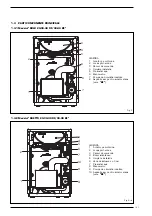
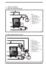
Страница 69: ...ion KEY 1 Gas oil burner 2 Bulb housing sheath 3 Control panel 4 Filling 5 Water switch 6 Hydrometer 7 System pump 8 Air intake for airtight burner BF versions KEY 1 Gas oil burner 2 Bulb housing sheath 3 Control panel 4 Instant tank 5 Filling 6 3 way diverter valve 7 Water switch 8 Hydrometer 9 System pump 10 Air intake for airtight burner BF versions ...

Страница 70: ...ty valve 4 Air relief valve 5 Expansion vessel 6 Gas oil burner 7 System pump 8 Hydrometer 9 Boiler drainer cock 10 Water switch KEY 1 Boiler body 2 Filling 3 Safety valve 4 Air relief valve 5 Expansion vessel 6 Gas oil burner 7 System pump 8 Hydrometer 9 Boiler drainer cock 10 C H water switch 11 D H W water switch 12 Instant tank 13 3 way diverter valve ...

Страница 71: ...mutes the diverter valve is immediately inserted supplying hot water practically at once To adjust water flow use the water pressure gauge flow regulator fig 5 Turn clockwise and the regulator reduces water supply consequently increasing the relevant temperatu re Turn counter clockwise and the regulator increases water supply consequently reducing the relevant temperature 2 2 3 Characteristics of ...

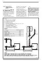
Страница 72: ... exhaust configuration are indicated in Table A Only use original SIME accessories and make sure that connections are correct as indicated in the instruc tions supplied with the accessories 2 3 3 Exhaust with separate flues ø 80 SOLO 30 BF DUETTO 30 BF boi 1 2 3 4 2 5 6 7 7 3 3 ø 80 125 min 715 Fig 6 KEY 1 Stainless steel coaxial flue L 886 code 8096220 2 a Stainless steel extension L 1000 code 80...

Страница 73: ...uivalenti max 7 6 m verticali 8 9 Fig 6 a TABLE B WARNING The maximum length of the suction flue should not exceed 16 equivalent meters The maximum length of the exhaust flue should not exceed 6 equivalent meters For roof mounted outputs always use the condensation recovery 4 and verify that the maximum vertical length of the flue does not exceed 7 6 meters without changes in direction KEY 1 Exhau...

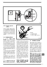
Страница 74: ...urner differently from the factory settings this should be done by authorised per sonnel following the instructions pro vided below Remove the shell door to access the burner unit s controls 2 5 1 Air lock adjustment To adjust the air lock loosen the screw 1 fig 8 and slide the graduated scale 2 fig 8 indicating the position air lock position The values for adjustment of each unit are given in poi...

Страница 75: ...efore te correct fuel temperature has been reached When it is started again enough time will have passed 2 3 minutes for the fuel to have reached the correct tem perature for start up SOLO 40 OF BF DUETTO 40 OF BF model have no heater unit as it is not required 2 7 ELECTRICAL CONNECTION The boiler is supplied with an electric cable and the electric power supply to the boiler must be 230V 50Hz sing...

Страница 76: ...oom stat C RVA 43 222 unit connectors optional SS Boiler immersion probe QA721 optional SC Heater immersion probe QA721 optional SE External temperature probe QAC31 optional UA Room unit QAA70 optional PB Boiler pump OP Time programmer NOTE When connecting the room stat TA remove the bridge between terminals 4 5 When connecting the RVA 43 222 unit remove the brid ge between terminals 4 5 and 4 6 W...

Страница 77: ... out warning light PA Water switch P Pump system B Burner TA Room stat VD Diverter valve C RVA 43 222 unit connectors optional SS Boiler immersion probe QA721 optional SC Heater immersion probe QA721 optional SE External temperature probe QAC31 optional UA Room unit QAA70 optional OP Time programmer NOTE When connecting the room stat TA remove the bridge between terminals 7 8 When connecting the R...

Страница 78: ...tion transform Gas oil valve Flame Stop light Normal Stopped due to failure to ignite NOTE On DUETTO 30 OF BF without stat the heater is always fed in winter position 5 s 12 s 12 s Consensus for start up Motor Ignition transform Gas oil valve Flame Stop light 2 7 4 SOLO 40 OF BF DUETTO 40 OF BF functional diagram Normal Stopped due to failure to ignite ...

Страница 79: ...the power supply Disconnect the Molex connector Push the button 1 while simultane ously turning the actuator anticlock wise to remove it from the valve body To reassemble the actuator perform the same procedure in reverse WARNING In the event of a fault the switch valve can be operated in intermediate mode by pushing the manual opening valve 2 until it is locked in position halfway along its trave...

Страница 80: ...ht hand shell which is held in place by four screws taking care not to damage the O ring seal OR To dismantle the nozzle holder and heater unit proceed as follows open the cover which is held in place by a screw and remove the heater cables 1 fig 15 a pro tected by a heat resistant sheath remove the fairlead and pass the cables through the hole remove the two cables from the ignition electrodes fa...

Страница 81: ...ean the remaining components of the combustion head of eventual deposits Upon completion re assemble the unit in the opposite way as described above taking care to respect the indicated measure ments 4 7 3 Substitution of nozzle The nozzle should be substituted at the beginning of every heating system for guaranteeing the correct fuel flow and a good spray efficiency The nozzle is substituted in t...

Страница 82: ... flame detection the air calibration and the function of the appliance Difficulty in regulating the burner and or lack of yield Check the regular flow of fuel the cleanness of the boiler the non obstruction of the smoke duct the real input supplied by the burner and its cleanness dust The boiler gets dirty easily Check the burner regulator smoke analysis the fuel quantity the flue obstruction and ...

Страница 83: ...ow a minimum working tempera ture of 60 C fig 21 SAFETY STAT The safety stat is of the manually resetting type and opens causing the main burner to turn off immediately whenever the temperature of 110 C is exceeded in the boiler To restore boil er operation unscrew the black cap and reset the button fig 21 Should the appliance lock out again USER INSTRUCTIONS WARNINGS In case of fault and or incor...

Страница 84: ...ater tap if the boiler remains inoperative for a long period SYSTEM FILLING Check periodically that the hydrometer has pressure values at a switched off system of 1 1 2 bar If the orange water pressure gauge light turns on inhibiting boiler opera tions restore operations by turning the supply tap counter clockwise After the operation check that the tap is properly closed fig 24 Should the pressure...

Страница 85: ...trouvent à proximité immédiate de la chaudière S assurer que le raccordement électrique a été effectué correctement et que le câble de terre est relié à une bonne installation de terre Vérifier que le conduit d évacuation des produits de la combustion est libre S assurer que les vannes éventuelles sont ouvertes S assurer que l installation a été remplie d eau et qu elle est bien purgée Vérifier qu...

Страница 86: ...c brûleur à combustion étanche Veilliez respecter les instructions de ce manuel pour effectuer une installation correcte et garantir le fonctionnement parfait de l appareil 1 DESCRIPTION DE LA CHAUDIERE 1 2 DIMENSIONS Fig 1 SOLO 20 OF SOLO 30 40 OF BF DUETTO 20 30 40 OF 30 40 BF P Profondeur 650 750 30 OF BF 850 40 OF BF 650 20 OF 750 30 OF BF 850 40 OF BF M Départ chauffage G 1 UNI ISO 228 1 G 1 ...

Страница 87: ... 46 3 CO2 12 5 12 5 12 5 Température maxi de service C 95 95 95 Puissance électrique absorbée OF BF W 220 200 230 180 210 Plage de réglage chauffage C 45 85 45 85 45 85 Production eau sanitaire Débit sanitaire spécifique EN625 l min Débit sanitaire continu t 30 C l h Débit sanitaire mini l min Pression maxi de service du ballon bar Brûleur à mazout Injecteur du brûleur 0 50 0 60 60 W 0 60 0 75 60 ...

Страница 88: ...orbée OF BF W 220 205 235 185 215 Plage de réglage chauffage C 45 85 45 85 45 85 Production eau sanitaire Débit sanitaire spécifique EN625 l min 9 7 8 7 12 5 11 0 14 8 14 2 Débit sanitaire continu t 30 C l h 670 590 890 780 1 000 1 000 Débit sanitaire mini l min 2 5 2 5 2 5 Pression maxi de service du ballon bar 6 6 6 Brûleur à mazout Injecteur du brûleur 0 60 60 W 0 75 60 W 0 85 60 W 0 50 60 W 0 ...

Страница 89: ...e de logement des bulles 3 Panneau de commande 4 Remplissage 5 Pressostat eau 6 Hydromètre 7 Pompe installation 8 Aspiration air brûleur étanche version BF LEGENDE 1 Brûleur à mazout 2 Gaine de logement des bulles 3 Panneau de commande 4 Ballon instantané 5 Remplissage 6 Vanne de dérivation à 3 voies 7 Pressostat eau 8 Hidromètre 9 Pompe installation 10 Aspiration air brûleur étanche version BF ...

Страница 90: ...5 Vase d expansion 6 Brûleur à mazout 7 Pompe installation 8 Hidromètre 9 Robinet vidange chaudière 10 Pressostat eau LEGENDE 1 Corps chaudière 2 Remplissage 3 Vanne de sécurité 4 Purgeur automatique 5 Vase d expansion 6 Brûleur à mazout 7 Pompe installation 8 Hidromètre 9 Robinet vidange chaudière 10 Pressostat eau installation 11 Pressostat eau sanitaire 12 Ballon instantané 13 Vanne de dérivati...

Страница 91: ...Quand on a besoin d eau sanitaire l aquastat qui commute la vanne de dévia tion se déclenche instantanément pour permettre l utilisation presque immédiate de l eau chaude Pour régler le débit de l eau sanitaire agir sur le régulateur de débit du pres sostat de l eau fig 5 En vissant le régulateur dans le sens des aiguilles d une montre on réduit le débit de prélèvement de l eau sani taire en augme...

Страница 92: ...s être supérieure à 7 0 mètres équiva lents Les pertes de charge en mètres pour chaque accessoire à utiliser dans la configuration d éva cuation figurent dans le Tableau A Utiliser exclusivement des accessoires originaux SIME et s assurer que le rac cord est effectué de manière correc te comme indiqué par les instructions fournies à titre de complément des accessoires 2 3 3 Évacuatio fumées par co...

Страница 93: ... 7 6 m verticali 8 9 Fig 6 a TABLEAU B ATTENTION La longueur maximum du conduit d aspiration ne devra pas être supérieure à 16 mètres équivalents La longueur maximum du conduit d évacuation ne devra pas être supérieur à 6 mètres équivalents Dans les sorties avec évacuation sur le toit utiliser toujours le dispositif de récupération de la condensation 4 et la longueur verticale du conduit sans chan...

Страница 94: ... Si l installation requiert des réglages différents de ceux faits en usine ceux ci doivent être effectués exclusive ment par un personnel autorisé et dans le respect des instructions ci dessous pour accéder aux organes de réglage de unité de combustion enlever la porte de la jaquette fig 12 2 5 1 Réglage du clapet d air Pour effectuer le réglage du clapet d air agir sur la vis 1 fig 8 et faire cou...

Страница 95: ...nnement commence avant que le combustible ait atteint la température optimale Au départ sui vant un certain temps se sera écoulé 2 3 minutes suffisant pour créer les conditions idéales de démarrage Le groupe chauffant n est pas monté sur les versions SOLO 40 OF BF DUETTO 40 OF BF car il n est pas nécessaire 2 7 RACCORDEMENT ELECTRIQUE La chaudière est munie d un câble élec trique d alimentation et...

Страница 96: ...leur TA Tharmostat d ambiance C Connecteurs centrale RVA 43 222 optionnel SS Sonde immersion bouilleur QAZ21 optionnel SC Sonde immersion chaudière QAZ21 optionnel SE Sonde température externe QAC31 optionnel UA Unité ambiante QAA70 optionnel PB Pompe bouilleur OP Horloge de programmation NOTE En reliant le thermostat ambiant TA retirer le cavalier entre les bornes 4 5 En reliant la centrale RVA 4...

Страница 97: ...blocage du brûleur PA Pressostat eau P Pompe installation B Bruleur TA Tharmostat d ambiance VD Vanne de dérivation C Connecteurs centrale RVA 43 222 optionnel SS Sonde immersion bouilleur QAZ21 optionnel SC Sonde immersion chaudière QAZ21 optionnel SE Sonde température externe QAC31 optionnel UA Unité ambiante QAA70 optionnel OP Horloge de programmation NOTE En reliant le thermostat ambiant TA re...

Страница 98: ...age Vanne mazout Flamme Lampe blocage Normale Blocage normal dû au manque d allumage NOTA Dans la version DUETTO 30 OF BF sans thermostat le réchauffeur est toujours actif en hiver 5 s 12 s 12 s Accord démarrage Moteur Transformateur allumage Vanne mazout Flamme Lampe blocage 2 7 5 Diagramme de fonctionnement SOLO 40 OF BF DUETTO 40 OF BF Normale Blocage normal dû au manque d allumage ...

Страница 99: ...sser le levier d ouverture manuelle 2 jusqu au blocage à mi course De cette manière les deux sorties restent partiellement ouvertes chauffage et sanitaire 3 1 DIMENSIONS DE LA CHAMBRE DE COMBUSTION La chambre de combustion est à pas sage direct elle est conforme à la norme EN 303 3 annexe E Les dimensions sont indiquées fig 10 Un panneau de protection spécial est appliqué sur la paroi interne de l...

Страница 100: ...x vis latérales et enle ver la gaine droite bloquée au moyen de quatre vis en faisant attention à ne pas abîmer les joints d étanchéité OR Pour démonter le dispositif d écla boussures et le groupe chauffant opérer de la façon suivante ouvrir le couvercle de l installation bloqué au moyen d une vis déta cher les câbles du réchauffeur 1 fig 15 a protégés par une gaine thermorésistante et les faire p...

Страница 101: ...urbulence Nettoyer soigneusement les élec trodes d allumage Nettoyer soigneusement la résistan ce photoélectrique en enlevant toute trace de saleté sur sa surface Nettoyer les autres pièces de la tête de combustion en enlevant toute incrustation A la fin de ces opérations remonter le tout en agissant en sens inverse et en ayant soin de conserver les mesures indiquées 4 7 3 Remplacement de le injec...

Страница 102: ... brûleur s allume régulièrement mais s éteint immédiatement Contrôler la détection de la flamme le tarage de l air et le fonctionne ment de l appareillage Réglage difficile du brûleur et ou absence de rendement Contrôler le flux régulier de combus tible la propreté du générateur la propreté du conduit d évacuation des fumées la puissance réelle four nie par le brûleur et sa propreté poussière Le g...

Страница 103: ...ra ture minimale de travail de 60 C fig 21 AQUASTAT DE SECURITE L aquastat de sécurité à réarmement manuel se déclenche en provoquant l extinction immédiate du brûleur quand la température dépasse 110 C Pour faire repartir l appareil dévisser le capuchon de protection et appuyer sur le bouton poussoir qui se trouve au dessous fig 22 INSTRUCTIONS DESTINEES A L UTILISATEUR MISE EN GARDE En cas de pa...

Страница 104: ...les robinets du combustible et de l eau de l installation thermique si le générateur doit rester au repos pen dant une longue période REMPLISSAGE DE L INSTALLATION Vérifier périodiquement que les valeurs de pression de l hydromètre sur l ins tallation froide sont comprises entre 1 et 1 2 bar Au cas où le témoin orange s allumerait à la suite de l intervention du pressostat de l eau en bloquant le ...

Страница 105: ...ialen in de onmiddellijke nabijheid van de ketel bevinden Zich ervan verzekeren dat de elektrische aansluiting op de juiste wijze uitgevoerd is en dat de ketel op een deugdelijk geaard stopcontact aangesloten is Controleren of de afvoerleiding van de verbrandingsprodukten vrij is Zich ervan verzekeren dat eventuele afsluiters open zijn Zich ervan verzekeren dat de installatie met water gevuld is e...

Страница 106: ...er met gesloten verbrandingska mer Neem de aanwijzingen die in deze handleiding opgenomen zijn in acht om er zeker van te zijn dat het toestel op de juiste manier geïnstalleerd wordt en perfect func tioneert 104 1 BESCHRIJVING VAN DE KETEL 1 2 AFMETINGEN Fig 1 SOLO 20 OF SOLO 30 40 OF BF DUETTO 20 30 40 OF 30 40 BF P Diepte 650 750 30 OF BF 850 40 OF BF 650 20 OF 750 30 OF BF 850 40 OF BF M Toevoe...

Страница 107: ... 41 4 35 9 42 9 52 8 46 3 CO2 12 5 12 5 12 5 Maximum bedrijfstemperatuur C 95 95 95 Elektrisch vermogen OF BF W 220 200 230 180 210 Regelberek verwarming C 45 85 45 85 45 85 Sanitair watervoorziening Specifiek sanitair debiet EN 625 l min Continu sanitair debiet t 30 C l h Minimum debiet sanitair water l min Maximum bedrijfsdruk boiler bar Stookoliebrander Branderinspuitstuk 0 50 0 60 60 W 0 60 0 ...

Страница 108: ...ktrisch vermogen OF BF W 220 205 235 185 215 Regelberek verwarming C 45 85 45 85 45 85 Sanitair watervoorziening Specifiek sanitair debiet EN625 l min 9 7 8 7 12 5 11 0 14 8 14 2 Continu sanitair debiet t 30 C l h 670 590 890 780 1 000 1 000 Minimum debiet sanitair water l min 2 5 2 5 2 5 Maximum bedrijfsdruk boiler bar 6 6 6 Stookoliebrander Branderinspuitstuk 0 60 60 W 0 75 60 W 0 85 60 W 0 50 6...

Страница 109: ...1 Stookoliebrander 2 Mantel sonde 3 Bedieningspaneel 4 Vullen 5 Waterpressostaat 6 Hydrometer 7 Circulatiepomp 8 Luchtaanzuiging voor gesloten brander versie BF LEGENDE 1 Stookoliebrander 2 Mantel sonde 3 Bedieningspaneel 4 Doorstroomboiler 5 Vullen 6 Driewegwisselklep 7 Waterpressostaat 8 Hydrometer 9 Circulatiepomp 10 Luchtaanzuiging voor gesloten brander versie BF ...

Страница 110: ...tluchtingsklep 5 Expansievat 6 Stookoliebrander 7 Circulatiepomp 8 Hydrometer 9 Afvoerkraan ketel 10 Waterpressostaat LEGENDE 1 Ketellichaam 2 Vullen 3 Veiligheidsklep ketel 4 Automatische ontluchtingsklep 5 Expansievat 6 Stookoliebrander 7 Circulatiepomp 8 Hydrometer 9 Afvoerkraan ketel 10 Waterpressostaat installatie 11 Waterpressostaat sanitair 12 Doorstroomboiler 13 Driewegwisselklep ...

Страница 111: ...endel schroef van de terugslagkleppen hori zontaal houden Na het vullen moet u de schroef weer in de oorspronkelijke stand zetten Na afloop van deze han deling moet u controleren of de vul kraan dicht is fig 4 2 2 2 Sanitair warmwatervoorziening DUETTO OF BF Bij het model DUETTO OF BF treedt bij de vraag naar sanitair warm water de pressostaat onmiddellijk in werking die ervoor zorgt dat de driewe...

Страница 112: ...aangege ven verder geen bijzondere aanslui tingen 2 3 2 Rookgasafvoer met coaxiale leiding ø 80 125 De BF ketels zijn geschikt voor aan sluiting op roestvrij stalen coaxiale afvoerleidingen ø 80 125 die geri cht kunnen worden volgens de eisen van de ruimte fig 6 De maximale lengte voor de leiding is 7 meter Het drukverlies in meters voor ieder afzonderlijk in de afvoeropstelling te gebruiken onder...

Страница 113: ... equivalenti max 16 m equivalenti max 7 6 m verticali 8 9 Fig 6 a TABEL B LET OP De toegestane maximum lengte van de aanzuigleiding mag niet langer zijn dan 16 equivalente meter De toegestane maximum lengte van de afvoerleiding mag niet langer zijn dan 6 equivalente meter Bij dakuitlaten moet altijd de condensaatopvangvoorziening 4 toegepast worden en de verticale lengte van de leiding zonder van ...

Страница 114: ...ruk ter hoogte van de zee spiegel Wanneer de installatie afstellingen vereist die afwijken van die van de fabriek dan mag dit uitsluitend door bevoegd personeel uitgevoerd worden dat daarbij de hieronder vermelde aanwijzingen aan moet houden Om bij de afstelorganen van de ver brandingseenheid te kunnen komen moet de deur van de mantel verwij derd worden 2 5 1 Afstelling van de luchtklep Om de luch...

Страница 115: ...der geblokkeerd wordt omdat de werkingscyclus begint voordat de brandstof de optimale tem peratuur bereikt heeft Als het toestel daarna in werking gesteld zal worden zal de nodige tijd verstreken zijn 2 3 minuten om de ideale omstandighe den voor de ontsteking te creëren Het verwarmingsblok is niet gemon teerd op de modellen SOLO 40 OF BF DUETTO 40 OF BF omdat dit niet nodig is 2 7 ELEKTRISCHE AAN...

Страница 116: ...ander TA Kamerthermostaat C Connectoren RVA regelaar 43 222 optioneel SS Immersievoeler boiler QAZ21 optioneel SC Immersievoeler ketel QAZ21 optioneel SE Voeler buitentemperatuur QAC31 optioneel UA Kamereenheid QAA70 optioneel PB Pomp boiler OP Programmerklok OPMERKINGEN Verwijder bij het aansluiten van de kamerthermostaat TA de brug tussen de klemmen 7 8 Verwijder de bruggen 7 8 en 17 18 bij het ...

Страница 117: ...ampje blokkering brander PA Waterpressostaat P Pomp installatie B Brander TA Kamerthermostaat VD Wisselklep C Connectoren RVA regelaar 43 222 optioneel SS Immersievoeler boiler QAZ21 optioneel SC Immersievoeler ketel QAZ21 optioneel SE Voeler buitentemperatuur QAC31 optioneel UA Kamereenheid QAA70 optioneel OP Programmerklok OPMERKINGEN Verwijder bij het aansluiten van de kamerthermostaat TA de br...

Страница 118: ...okkeringslampje Normaal Blokkering vanwege niet plaatsgevonden ontsteking OPMERKING Bij het model DUETTO 30 OF BF dat niet van een thermostaat voorzien is is het verwarmingsapparaat in de winter altijd in werking 5 s 12 s 12 s Starttoestemming Motor Ontstekingstransformator Stookolieklep Vlam Blokkeringslampje 2 7 4 Werkingsdiagram SOLO 40 OF BF DUETTO 40 OF BF Normaal Blokkering vanwege niet plaa...

Страница 119: ...volgt te werk gaan fig 13 Schakel de stroontoevoer uit Koppel de Molex stekker los Druk op de knop 1 en draai tegelij kertijd het aandrijfelement tegen de wijzers van de klok in naar links om het element uit het kleplichaam te kunnen trekken Om het aandrijfelement weer te monteren moet u in de omgekeerde volgorde te werk gaan LET OP In geval van een storing is het mogelijk om de omloopklep toch op...

Страница 120: ...roe ven aan de zijkant bevestigd is ver wijderen en de rechterhelft verwijde ren die door vier schroeven op zijn plaats gehouden wordt waarbij u op moet passen dat de dichtingsringen O ringen niet beschadigd worden Om de inspuitstukhouder en het ver warmingsblok te demonteren moet u als volgt te werk gaan doe de kap van het toestel die door een schroef op zijn plaats gehouden wordt open maak de ka...

Страница 121: ...erbrandingskop te reinigen moet u als volgt te werk gaan fig 17 Koppel de hoogspanningskabels van de elektroden los Draai de bevestigingsschroeven van de steun van de propeller los en ver wijder de steun Borstel de propeller turbulentie schijf voorzichtig af Maak de ontstekingselektroden goed schoon Ontdoe de fotocel goed van eventu ele vuilaanslag die zich op het opper vlak ervan afgezet heeft On...

Страница 122: ...roleer de elektrische aanslui tingen Controleer of de brandstof goed wordt toegevoerd of de filters en het inspuitstuk schoon zijn en of de leiding is contlucht Controleer of de ontstekingsvonken goed gevormd worden en of de bran derautomaat goed functioneert De brander gaat goed branden maar gaat meteen daarna uit Controleer de waarneming van de vlam de instelling van de lucht en de werking van d...

Страница 123: ...s aquastaat die een handmatige reset functie heeft in waardoor de brander onmiddellijk gedoofd wordt Om de ketel weer in werking te stellen moet u het zwarte kapje eraf schroeven en moet u op het knopje dat zich daaron der bevindt drukken fig 22 Als dit vaak gebeurt moet u een erkende vakman inschakelen om dit na te kijken DE BRANDER ONTGRENDELEN Als er storingen in de ontsteking of in de werking ...

Страница 124: ...s de installatie koud is een druk waarde tussen de 1 en de 1 2 bar uit wijst In het geval dat het oranje con trolelampje voor activering van de waterpressostaat aangaat waardoor de werking van de brander wordt geblokkeerd kunt u de druk herstellen door de vulkraan tegen de klok in te draaien Na afloop van deze handeling moet u controleren of de kraan goed dicht gedraaid is fig 24 Als de druk boven...

Страница 125: ... daca exista lichide sau materiale inflamabile in apropiereamicrocentralei Asigurati va ca legaturile electrice au fost efectuate corect inclusivimpamantarea Verificati ca conducta de evacuare gaze arse sa nu fie obturata Asgurati va ca robinetele sa fie deschise pe tur si retur Asigurati va ca s a efectuat umplerea cu apa si aerisirea instalatiei Verificati ca pompa de circulatie sa nu fie blocat...

Страница 126: ...ere etansa Pentru executarea corecta a ope ratiunilor de instalare si pentru o functionare perfecta a microcen tralei respectati instructiunile descrise in acest manual 124 1 DESCRIEREA MICROCENTRALEI 1 2 DIMENSIUNI Fig 1 SOLO 20 OF SOLO 30 40 OF BF DUETTO 20 30 40 OF 30 40 BF P Adancime 650 750 30 OF BF 850 40 OF BF 650 20 OF 750 30 OF BF 850 40 OF BF M Tur instalatie G 1 UNI ISO 228 1 G 1 UNI IS...

Страница 127: ... 160 185 Debit masic gaze arse mini maxi m3n h 24 0 31 6 26 4 32 4 41 4 35 9 42 9 52 8 46 3 CO2 12 5 12 5 12 5 Temperatura maxima de functionare C 95 95 95 Tensiune electrica absorbita OF BF W 220 200 230 180 210 Domeniul de reglare C 45 85 45 85 45 85 Debit ACM Debit specific ACM EN 625 l min Debit continu ACM Dt 30 C l h Debit minim ACM l min Presiune maxima de functionare boiler bar Arzator pe ...

Страница 128: ... 8 46 3 CO2 12 5 12 5 12 5 Temperatura maxima de functionare C 95 95 95 Tensiune electrica absorbita OF BF W 220 205 235 185 215 Domeniul de reglare C 45 85 45 85 45 85 Debit ACM Debit specific ACM EN 625 l min 9 7 8 7 12 5 11 0 14 8 14 2 Debit continu ACM Dt 30 C l h 670 590 890 780 1 000 1 000 Debit minim ACM l min 2 5 2 5 2 5 Presiune maxima de functionare boiler bar 6 6 6 Arzator pe motorina D...

Страница 129: ...ocas port sonde 3 Panoul de comanda 4 Umplere instalatie 5 Presostat apa 6 Manometru 7 Pompa de circulatie incalzire 8 Aspiratie aer pentru arzator etans vers BF LEGENDA 1 Arzator pe motorina 2 Locas port sonde 3 Panoul de comanda 4 Boiler istantaneu 5 Umplere instalatie 6 Vana deviatoare cu 3 cai 7 Presostat apa 8 Manometru 9 Pompa de circulatie incalzire 10 Aspiratie aer pentru arzator etans ver...

Страница 130: ...otorina 7 Pompa de circulatie instalatie 8 Manometru 9 Robinet pentru golire instalatie microcentrala 10 Presostat apa LEGENDA 1 Corpul cazanului 2 Umplere instalatie 3 Supapa de siguranta cazal 4 Dezaerator automat 5 Vas de expansiune 6 Arzator pe motorina 7 Pompa de circulatie instalatie 8 Manometru 9 Robinet pentru golire instalatie microcentrala 10 Presostat apa circuit de incalzire 11 Presost...

Страница 131: ...tm lent pentru a permite elimi narea bulelor de aer din instalatie prin respectivele orificii de aerisi re Pentru a facilita aceasta ope ratiune pozitionati orizontal fanta surubului de blocare a supapelor de retinere Dupa ce s a efectuat umplerea instalatiei repozitionati vertical fanta surubului de blocare a supapelor de retinere La sfarsi tul operatiunii verificati ca robine tul sa fie inchis f...

Страница 132: ...rala si cos 1 00 m pentru fiecare metru parcurs orizontal de racordului respectiv Microcentralele prezentate sunt de tipul B23 si nu necesita racorduri speciale cu exceptia racordului la cos descris 2 3 2 Cos de fum cu conducta coaxiala ø 80 125 Microcentralele versiunea BF sunt prevazute pentru racordarea la conducte de evacuare coaxiale din otel inox ø 80 125 care se pot orienta in directia cea ...

Страница 133: ... 3 10 2 5 6 min 700 max 16 m equivalenti max 16 m equivalenti max 7 6 m verticali 8 9 Fig 6 a TABELUL B ATENTIE Lungimea maxima a conductei de admisie nu trebuie sa depaseasca 16 metri echivalenti Lungimea maxima a conductei de evacuare nu trebuie sa depaseasca 6 metri echivalenti Pentru iesirile cu evacuare prin acoperis se va utiliza întotdeauna recuperatorul de condens 4 iar lungimea maxima ver...

Страница 134: ...tatea de combustie completa continand duzele si fiind prereglata din fabrica totusi se recomanda verifica rea parametrilor descrisi la paragraful 1 3 care fac referi re la presiunea atmosferica la nivelul marii In cazul in care instalatia necesita efectuarea unor reglaje diferite de cele efectuate din fabrica acestea pot fi efectuate doar de catre personal tehnic Autorizat respectand instructiunil...

Страница 135: ...ibil ca apr inderea arazatorului sa prezinte dificicultati in consecinta se poate produce blocarea functionarii acestuia intrucat ciclul de functio nare incepe inainte ajungerii com bustibilului la temperatura optima de ardere La o pornire succesiva a micro centralei acest inconvenient de pornire a arzatorului nu se va mai produce deoarece va exista o temporizare 2 3 minute suficien ta pentru a pe...

Страница 136: ...at apa P Pompa instalatie B Arzator TA Termostat de ambianta C Conectori regulator RVA 43 222 optional SS Sonda imersie boiler QAZ21 optional SC Sonda imersie cazan QAZ21 optional SE Sonda temperatura exterioara QAC31 optional UA Dispozitiv de ambianta QAA70 optional PB Pompa boiler OP Programator timp NOTE Pentru conectarea termostatului de ambianta TA scoateti puntea dintre bornele 4 5 Pentru co...

Страница 137: ...nta tensiune SB Lampa de semnalizare ce indica blocarea arzator PA Presostat apa P Pompa instalatie B Arzator TA Termostat de ambianta VD Vana deviatoare C Conectori regulator RVA 43 222 optional SS Sonda imersie boiler QAZ21 optional SC Sonda imersie cazan QAZ21 optional SE Sonda temperatura exterioara QAC31 optional UA Dispozitiv de ambianta QAA70 optional OP Programator timp NOTE Pentru conecta...

Страница 138: ...gheata Led semnalizarie blocare arzator Normal Blocaj datorat nerealizarii aprindereii NOTA La versiunea DUETTO 30 OF BF neprevazuta cu termostat preincalzitorul este mereu in functiune 5 s 12 s 12 s Permisie aprindere Motor Transformator de aprindere Electroventil pentru motorina Flacara supravegheata Led semnalizarie blocare arzator 2 7 4 Diagrama de functionare la modelele SOLO 40 OF BF DUETTO ...

Страница 139: ...entru demontarea motorului vanei deviatoare actionati dupa cum urmeaza figura 13 Decuplati alimentarea electrica Scoateti conectorul Molex Apasati tasta 1 si rotiti simul tan servomotorul in sens antior ar pentru a l extrage din corpul vanei Pantru remontarea servomoto rului actionati in sens invers ATENTIE In cazul avarierii vanei este posibila mentinerea in functiune a acesteia in pozi tia inter...

Страница 140: ...l figura 15 Pentru dezasamblarea arzatoru lui indepartati capacul ventilato rului prin desfacerea celor doua suruburi laterale de fixare si extrageti capacul de protectie lateral dreapta al arzatorului desfacand cele patru suruburi de fixare ale acestuia procedati cu atentie pentru a nu deteriora garniturile de etansare existen te Pentru demontarea suportului capului de ardere si a preincalzi toru...

Страница 141: ...espunzatoare Dupa efectuarea curatirii drumurilor de gaze arse montati turbulatoarele in pozitia ini tiala fig 16 4 7 2 Curatirea capului de ardere OPentru curatirea capului de ardere actionati dupa cum urme aza figura 17 Deconectati cablurile de alimen tare cu tensiune ale electrozilor Dsurubati cele doua suruburi de fixare ale suportului deflectorului si extrageti l Curatati cu atentie deflector...

Страница 142: ...erificati daca electrodul de apr indere produce scantei si daca automatul de ardere functione aza corect Arzatorul se aprinde corect dar se stinge imediat Verificati electrodul de sesizare flacara debitul de aer si functio narea corecta a supravegheto rului de flacara Reglarea arzatorului este difici la si sau aparatul nu functione aza la randamentul corespunza tor Verificati daca combustibilul aj...

Страница 143: ...vocand stingerea imediata a arzatorului in cazul in care temperatura apei depaseste 110 C Pentru repornirea micro centralei desurubati capacul negru de protectie si apasati butonul pozitionat sub capac figu ra 22 DEBLOCAREA ARZATORULUI In cazul in care microcentrala nu porneste sau arzatorul nu se apr inde acest lucru va fi semnalat de aprinderea ledului de pe panoul de comanda care indica blocare...

Страница 144: ...ar In cazul in care se aprinde led ul de semnalizare portocaliu care indica interventia presostatului de apa blocand functionarea arzato rului restabiliti presiunea rotind robinetul de presiune in sens antiorar La sfarsitul operatiei de umplere controlati ca robinetul sa fie inchis corect fig 24 In cazul in care valoraea presiunii a depasit limita prevazuta evacuati apa din instalatie actionand as...

Страница 145: ...vigenti in mate ria e rispondono per caratteristiche tecniche e funzionali alle prescrizioni delle norme UNI 7936 dicembre 1979 FA130 84 FA168 87 EN 303 1994 Le caldaie a gasolio sono inoltre conformi alla DIRETTIVA RENDIMENTI 92 42 CEE La ghisa grigia utilizzata è del tipo EN GJL 150 secondo la norma europea UNI EN 1561 Il sistema qualità aziendale è certificato secondo la norma UNI EN ISO 9001 2...

Страница 146: ......

Страница 147: ......

Страница 148: ...Cod 6276006B 01 07 Documentation Dpt Fonderie Sime S p A Via Garbo 27 37045 Legnago Vr Tel 39 0442 631111 Fax 39 0442 631292 www sime it ...

Отзывы: