


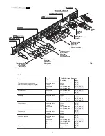


13
by pressing the ESC key, or when the time allowed for displaying
the on-screen menu has lapsed (set in the Set-up Menu).
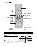
Inputs 5, 6, 7 and 8 can receive RGB and YCrCb signals, at 15
kHz, 32 kHz or higher. The association between the input and
the type of signal is made from the pull-down menu that appears
on the right of the < symbol after pressing the < key (Fig. 12b).
After selecting the signal coming from the source (by means of
the
and
keys), press MENU+/MENU - to confirm and close
the pull-down menu; on the right of the < symbol the value just
set will be displayed.
As with the other inputs, you can now select the input just set by
pressing the key >.
During the short time it takes to find the signal, a box appears
showing the signal requested. As soon as this is displayed,
additional information relating to video standard (for video
signals) or resolution (for graphic signals) and aspect appears
in the box.
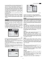
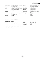
MAIN MENU
To access the main menu of the On Screen Display press the
MENU key on the keypad or the MENU+ or MENU- key on the
remote control.
The main menu is divided into three windows, PICTURE, IMAGE
and SET-UP, in which the various adjustments are grouped
according to the frequency used. With
and
select the line
corresponding to the adjustment to be made (Fig. 13).
The various menus only offer pertinent adjustments, according
to the type of input signal displayed (e.g. certain typical
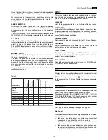
Picture
Image
Setup
Contrast
Color
Tint
Sharpness
Filter
Cinema Mode
Video Type
50
50
50
3
2
Off
Normal
Auto
VCR
Brightness
60
Color Temperature
Gamma Correction
Position
Y/C Delay
Magnification
1
Aspect
Picture
Image
Setup
Color Temperature
Gamma Correction
Position
Y/C Delay
Magnification
1
Aspect
Normal
Anamorphic
Letterbox
Panoramic
Pixel to pixel
User 1
User 2
User 3
Picture
Image
Setup
adjustments for video signals, not necessary for graphic signals,
do not appear on the menus, and vice versa).
Some adjustments (e.g.BRIGHTNESS and CONTRAST) are
differentiated by a numerical value, which can be changed, within
set limits, using the keys
/
.
For others (e.g. VIDEO TYPE) you can choose between two
options presented on the same line (and selectable using the
keys
/
).
Other adjustments (marked by the < symbol) provide submenus,
which appear as a superimposed window in which the selection
is made with the
/
(Fig. 14).
These submenus are accessed by pressing the < key, while exit
and return to the upper level occurs by pressing MENU+/-.
Press ESC on the remote control or keypad to interrupt the menu
display or wait for it to disappear automatically after the number
of seconds set on the SET-UP page.
PICTURE
This menu contains the adjustments that affect image quality.
Adjustments that are not available for a given input do not appear
on the menu. Table 4 summarises the adjustments available for
each input. For a complete table of the on-screen menus, consult
‘On screen menu layouts’ in the section “Additional Information.”
BRIGHTNESS
Adjusts the level of light associated to the black parts of the
image (black level), without affecting the white parts. By
increasing this value the darker parts of the image will become
sharper. To make the correct adjustment the grey scale signal
display can be useful, endeavouring to make the black level and
the level just above it distinct. Alternatively, you can use a scene
with black objects close to other dark objects.
CONTRAST
Adjusts the level of light associated with the white parts of the
image (white level) without affecting the black parts.
Displaying a grey scale can help in making the correct
adjustment, endeavouring to make the white level and the level
just below it distinct. Alternatively, you can use a scene in which
there are well-lit white objects surrounded by light objects that
are illuminated less intensely.
COLOUR
This adjustment (also called Saturation) increases or decreases
the colour intensity of the image. At the value of zero, a colour
image will appear in black and white. Increasing the value, it will
be necessary to find the point where the colours appear natural:
the skin tone of a person or the green of the grass in a landscape
are good references.
TINT
Adjusts the colour purity of the image. It essentially expresses
the ratio between red and green in an image.
On decreasing this value, the red content of the image will
increase; increasing the value, the green content will increase.
The skin tone of a person or a test pattern with colour bars can
be used when making this adjustment.
SHARPNESS
Increases or decreases the sharpness of the image by
processing the signal.
On decreasing this value, the details of the image will appear
softer, while increasing it will make them more defined, and the
edges of the object become sharper.
However, too high a value could make the image appear ‘noisy’
and highlight the outlines of the object in a unnatural way.
Fig. 13
Fig. 14a
Fig. 14b


