background image

Содержание 1011B

Страница 1: ...s dimensions areonly I x 3 x 4 in Powerinput exceeds260 watts P E P on singlesideband 60 watts on AM and 180 wattsonCW TheModell 011B includesautomaticgaincontrol AGC automaticlevelcon trol ALC andgrid blockkeying The Model 1011 B generates a single sideband signal by means of a crystal lattice filter and the transceive operation automatically tunes the transmitter to the received fre quency Provi...

Страница 2: ...14 l2AX7 MicrophoneAmplifier CARRIER SUPPRESSION Carrier suppression greater than 50 db RECEIVER SENSITIVITY Less than 0 5 microvolt at 50 ohms impedance for signal plus noise to noise ratio of 10 db TRANSISTOR COMPLEMENT Ql 2N706 Oscillator Q2 2NS130Buffer Q3 2N706 CarrierOscillator AUDIO OUTPUT AND RESPONSE Audio output 3 watts to 3 2 ohm load Responseessen tially flat from 300 to 3000 cps in bo...

Страница 3: ...e microphonesonly The choiceofmicrophoneis important for good speechquality and should be givenseriouscon sideration The crystallattice filter in the transceiver pro vides all the restriction necessary on audio response and further restrictionin the microphoneis not required It is more important to have amicrophonewith a smooth flat responsethroughout the speechrange The microphone plug mustbe a s...

Страница 4: ...G I TWO 12 24 HEX HEAD SCREWS _ y JII IIIIII 10 x 3 4 Mf l AL 8 SEAT SCRE lS 4 PLACES REAR BRACKET PLUGS INTO SLOT MADE BY FLAT WASHER BETWEENCHASSIS AND BOTTOM COVER TRANSMISSION HUMP TRANSCEIVER BOTTOM VIEW MOBILE MOUNTING SIDE VIEW FIGURE 1 MOBILE MOUNTING ON TRANSMISSION HUMP UNDER DASH 4 ...

Страница 5: ...rier frequencyinto the Cuterpassband Carrier is fully inserted P A cathode resistor R406 is switched in the circuit reducing input power Transmitteris tuned in this position CWtrans missions madein thisposition MIC GAIN Controls potentiometer R1404in the grid of V14A andcontrols amountof audio to the balanced modu lator R F GAIN ControlsvariableresistorRS05 commonin thegrids of ReceiverMixer V6 RF...

Страница 6: ... then transmitoff frequency and your voice will soundlower thannormalpitch to the otherstation He will probably retune his dial to make you soun dright If you keep this up you will graduallywaltz one another acrossthe band If both of you aremistuningto anun natural higherpitch you will waltzacross the bandtwiceas fast And someonewill no doubtbeaccused of frequency drift I WARNING_ Dangeroushigh vo...

Страница 7: ... permissibleidling cur rent rangeis 30 to 50 ma If theidling currenttends to creep upwardslightlywith warm up setit at30ma Excessivecreepindicatesthat the P A tube is gassy and may needto be replacedsoon This adjustment shouldnot berequiredoften 0 Zero beatthe carrierwith thetuningdial Turnoff the SPOT switch The AM stationshouldbe on frequency with excel lentvoicereception TRANSMITTER TUNING I CA...

Страница 8: ...N CD Tune the transmitterto full output asyou would for SSBtransmittertuning y Inserta CW key in the Key Jackonthe rearpanelof the transceiver Theprecedingstepscompletethe TransmitterTuning procedurefor SSB Returnthe Function Switchto theREC position 0 In CW operation it is necessaryto switch the Func tion Switch to the TUNE CW position hen trans mitting and back to the REC position while receivin...

Страница 9: ...encou pled from the secondarywinding of Tl30l to the crystal filter which suppresses the lower sideband and permits only the uppersidebandto befed to the First IF Amplifier V7 The carrier frequencyis generatedat approximately 5500 0KHz nonnal sideband Withtheoppositesideband crystal the carrier crystal frequency will be 5504 6 KHz and this positionsthe doublesidebandsignalon the other sideof the f...

Страница 10: ... MIC AMP 1 2 12AX7 V13 BAL MOD 6JH8 XTAL FILTER 5500 Xc L j FIGURE 3 BLOCK DIAGRAM TRANSMIT MODE I I I I V9A PRODUCT DET 1 212AX7 VB SECOND IFAMP 12BA6 L L___J I i 1 _J ANT V9B REC AFAMP 1 2 12 AX7 03 CAR OSC 2N706 V7 FIRST IFAMP 12BA6 V1 VFO AMP 12AU6 PI NET t XTAL FILTER 5500 Kc V6 REC MIXER 12BE6 V5 REC RFAMP 6BZ6 I FIGURE 4 BLOCK DIAGRAM RECEIVE MODE 10 Downloaded by RadioAmateur EU ...

Страница 11: ...ally 5500 0 KHz through IF amplifiers V7 andVB In the Product Detector V9A the IF signalisheterodyned With the carrierfrequencygeneratedby CarrierOscillator Q3 The resultantaudio is thenamplified by V9B which thencouplesto the AGCamplifier VIO andtheaudioout put stage VII The Siltronix 1011Bis capableof 180 watts P E P input under steady state two tone test conditions The peak envelopepower when v...

Страница 12: ...plate dissipationwill beapproximately 26 watts The6LF6 is rated at 40 watts continuous duty cycle in normal TV service n1US it canbe seenthat under normal operatingconditions the Power Amplifier tube in the 101lB isnot beingdrivenveryhard Note however that propermodulationlevelmustbemaintainedby correctset ting of Mic Gain and that the lengthof time in TUNEposi tion mustbelimited to not more than3...

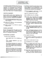
Страница 13: ...s LI0l L201 and 1301 for maximum reading Whenreadinggoeshigherthan80ma or so adjust CARRIER BALANCE control for 60 ma again S METERADJUSTMENT With the antennadisconnected R F GAIN control fully clockwise and METER switch in S METERposition set R70S located on the rear panel for zero meter reading Makesureno localsignals arebeingreceived Adjustcoils carefullyfor maximumpeak Exercise caution with CA...

Страница 14: ...FIGURE 6 SILTRONIX MODEL 10118 TOP VIEW 14 Downloaded by RadioAmateur EU ...

Страница 15: ......

Страница 16: ...xjmatley28 3MHz Key the transmitter with the Mic button and adjustthe CARRIER BALANCEcontrol for mini mumpoweramplifiercurrent S VFO Calibration Mter allowing approxjmatelyfive minutesfor warm up tune the dial to the 200KHz incrementfor any of the 10 meter rangesto be calibrated For CB calibration tune the dial to the 27 100KHz increment Usingthe 100 KHz crystal calibrator as a signalsource tune t...

Страница 17: ...Ohms 1 8 1 8 500 12 6AC 1 210 12 6AC 220 0 1 lSK VB 12BA6 2ndI F RVolts T Volts Ohms 1 7 1 7 110K 12 6AC 12 6AC 0 1 205 225 lSK V9 12AX7 Det AF R Volts T Volts Ohms 0 0 0 0 0 0 0 0 0 1 1 6 IlK 20 1 6 5K 1 9 0 10K 0 0 0 0 45 75K 0 0 0 0 0 0 0 0 0 0 0 300 6 3AC 6 3AC 0 2 215 0 10K 12 6AC 12 6AC 0 1 0 75 0 0 0 0 0 0 0 0 0 0 0 0 0 0 0 63 63 0 0 0 0 6 3AC 6 3AC 0 2 Via 6AU6 AGCAmp R Volts T Volts Ohms ...

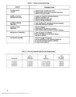
Страница 18: ...on 1 CarrierOscillator Q3 operatingon incorrectfrequency 2 Crystalfllter defectiveormistuned Insufficient Carrier Suppression 1 TubeV13 defective 2 Transformer T1301 defectiveor mistuned 3 Oirrier O i11ator Q3 operatingon incorrectfrequency Microphonicsin Transmitter r I iibes V13 and or V14 defective 2 IF coil1701 Defectiveor incorrectlyadjusted 3 Microphone defective Low Receiver Sensitivity 1 T...

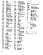
Страница 19: ...Rl04 56 Ohm R20l 27K R202 lOOK R203 lOOK R204 10K 2W R205 470K R206 2 7K R30l lOOK R302 lOOK R303 10 Ohm R304 100Ohm R40l 100Ohm R402 25K BiasPot R403 4 7K R404 IK R405 3 Ohm 5W R406 100Ohm SW R407 2 7K R408 l5K RSOI lOOK RSO2 220K RS03 470 Ohm RS04 10K RS05 25KR F GainPot RS06 10K RS07 470K R601 47K R701 1 5K R702 33K 2W R703 lK R704 47K R705 25K 8 MeterZero Pot R706 l5K R707 47K 2W R708 lOOK R80...

Страница 20: ... 01 80 20 500V Disc 01 80 20 500V Disc 01 80 20 500V Disc 5Opf Disc 5Opf Disc 220pf Disc 00220 IKV Disc ISOpf Disc 2 MFD 450V 50Opf Disc 00220 lKV Disc 05 200V Mylar 05 200V Mylar 001 20 Disc 01 80 20 SOOVDisc 001 20 Disc 001 20 Disc 001 20 Disc 220pf Disc 002 20 I KV Disc 500pfDisc 01 10 1 OOOV Tubular 50pf Disc 6Opf Trimmer I 5OpfDisc 12BA6VFO Amp 12BE6Trans Mixer 6GK6 Driver 6LF6 PowerAmp 6BZ6R...

Страница 21: ... warranty policy for Ii period of90 days Thiswarranty is valid only if the enclosed card isproperlyfilled in andmailedto thefactory within ten days of date of purchase Do not ship to the factory without prior authorization This warranty is IOn tedto repairingor replacingonly the defectiv eparts and is not validif the equipmenthasbeentamperedwith misusedor damaged A11 returnsfor repairsmustbe sent ...

Страница 22: ...Downloaded by RadioAmateur EU ...

Страница 23: ...Downloaded by RadioAmateur EU ...

Страница 24: ...T 1 J RCA 1 I J I I cms 2Mr I I _ I 0 i K 0 i 0 Dl111 I I I I I I I I I I I I I I _I I mc WF ...

Страница 25: ......

Страница 26: ... Il 11 J 1Z ...

Страница 27: ......

Страница 28: ......

Страница 29: ......

Страница 30: ......

Страница 31: ......

Страница 32: ...Downloaded by RadioAmateur EU ...

Отзывы: