


16
007-5900-001
3: System Operation and Monitoring
Front Panel Controls and LEDs
The control panel contains control buttons and status LEDs.
Figure 3-2
shows the components of
a control panel.
Figure 3-2
Control Panel Components
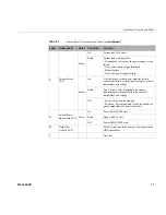
Table 3-1
describes the control panel components and their functions.
Table 3-1
Control Panel Components and Functions
Label
Button/LED
Color
Condition
Function
A
System ID
Button with LED
Blue
On
Highlights targeted system. Can be activated by the
button or software.
B
NMI Button
Used for diagnostics.
C
,
J
Network
Link/Activity
LEDs
Green
On
No access to LAN link.
Blink
LAN activity.
Off
No link.
D
Not used.
E
System Cold
Reset Button
When pressed, this button reboots and re-intializes
the system.
Содержание UV 20
Страница 1: ...SGI UV 20 System User Guide 007 5900 001 ...
Страница 3: ...007 5900 001 iii Record of Revision Version Description 001 February 2013 Original printing ...
Страница 4: ......
Страница 10: ......
Страница 58: ......
Страница 62: ......
Страница 64: ......
Страница 70: ......