UNOCODE 299
Operating manual - English
52
Copyright Silca 2002
Y
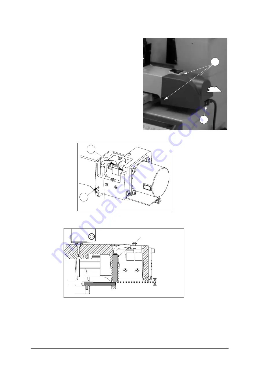
AXIS SENSOR REPLACEMENT
1) turn the machine off and unplug it from its power
supply cable.
2) raise the protective shield.
3) disconnect the (J1) Y axis cable from the carriage
4) remove the Y axis carriage cover by unscrewing
the 3 (B5) locking screws and pull the cover in the
direction shown in fig. 48.
5) disconnect the (M3) sensor’s connector (fig. 49).
6) slightly loosen the (M2) grub screw with the
provided allen key.
7) remove the faulty sensor and replace it with a
new one. Screw it in until it almost touches the
underlying rod (fig. 50). Tighten the (M2) grub
screw to lock the sensor into place.
8) connect the (M3) sensor’s connector.
9) replace the Y axis carriage cover.
10) connect the (J1) Y axis connecting wire to the
carriage.
Fig. 48
Fig. 49
Fig. 50
B5
J1
M3
M2
Y axis sensor
Y axis sensor
0,1 - 0,4 mm
Содержание Unocode 299
Страница 1: ...D425337XA vers 6 0 Operating manual...
Страница 62: ......
Страница 63: ...Operating manual English UNOCODE 299 Copyright Silca 2002 Appendix III UNOCODE 299 ELECTRICAL DIAGRAMS Ver 1 0...
Страница 64: ...Operating manual English UNOCODE 299 Copyright Silca 2002 Appendix IV...
Страница 65: ...Operating manual English UNOCODE 299 Copyright Silca 2002 Appendix V...
Страница 66: ...Operating manual English UNOCODE 299 VI Appendix Copyright Silca 2002...


