BRAVO MAXIMA II
Operating manual - English
14
Copyright Silca 2011
5.9
Checking and setting
The cutting tool on the BRAVO MAXIMA is the part used to cut the key blanks and should be periodically
checked and replaced, if necessary.
Every time the cutting tool is changed, and during periodical operational tests, check calibration.
5.10
Calibration
Calibration should be carried out whenever parameters must be set on the machine.
BRAVO MAXIMA requires two types of calibration:
depth
and
axis
.
Fig. 12
5.11
Gauging by electric contact
D
EPTH
CALIBRATION
:
Depth calibration is regulation of the cutting depth (fig.12). Proceed as follows:
1) Turn off the master switch (C) to operate safely and prevent activation of the cutting tool.
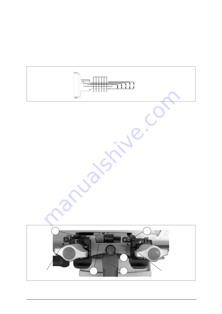
2) Position the electric contact templates on the clamps and proceed as follows:
a) ensure that the keys adhere to the clamps and that the callipers (K) are in full contact with the
stops.
b) to take the callipers into contact with the keys, rotate the drum (R) towards you (away from
you to return to the ideal position).
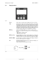
c) Press the I/O key on the display in order to turn it on.
d) Press the MODE key; the display will show the word OFF (no contact).
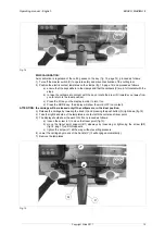
ATTENTION: the carriage will be released only if the callipers are in the ideal position.
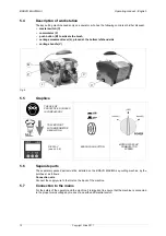
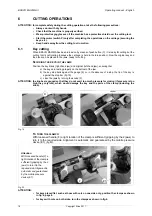
3) Release the carriage by lowering the knob (V) and pressing the push button (Q) right down (fig.13).
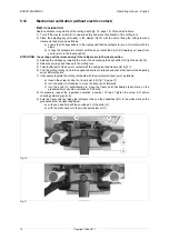
4) Raise the carriage and take up to the cutting tool.
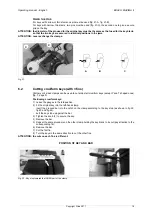
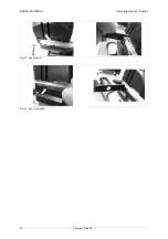
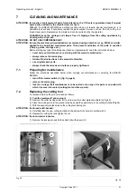
5) Take the templates in contact with cutter and tracer point (fig. 14, page 15).
6) The display should show the word ON; if not, proceed as follows:
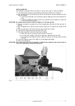
a) loosen the screw (J2) locking the tracer point (fig.18, pag.17).
b) turn the knob (O) clockwise to move the tracer point forwards.
c) turn the knob (O) anticlockwise to move the tracer point backwards.
7) Lock screw (J2) when ON appears.
8) Zero the tracer point by taking the reference index on the handwheel (O1) to the white mark on the
graduated drum, as described below:
a) with one hand hold still the knurled part of the knob (O).
b) with the other hand turn the mobile part below it (O1).
Fig. 13
6
4
8
9
0
cutting
I II III IV V VI
cutting
space
depth
R
Q
K
V
K
TEMPLATE (C)
TEMPLATE (T)
TRACER POINT SIDE
CUTTER SIDE


