background image

BRAVO MAXIMA II

Operating manual - English

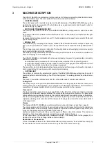
10

Copyright Silca 2011

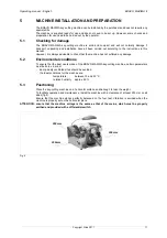
4

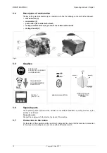
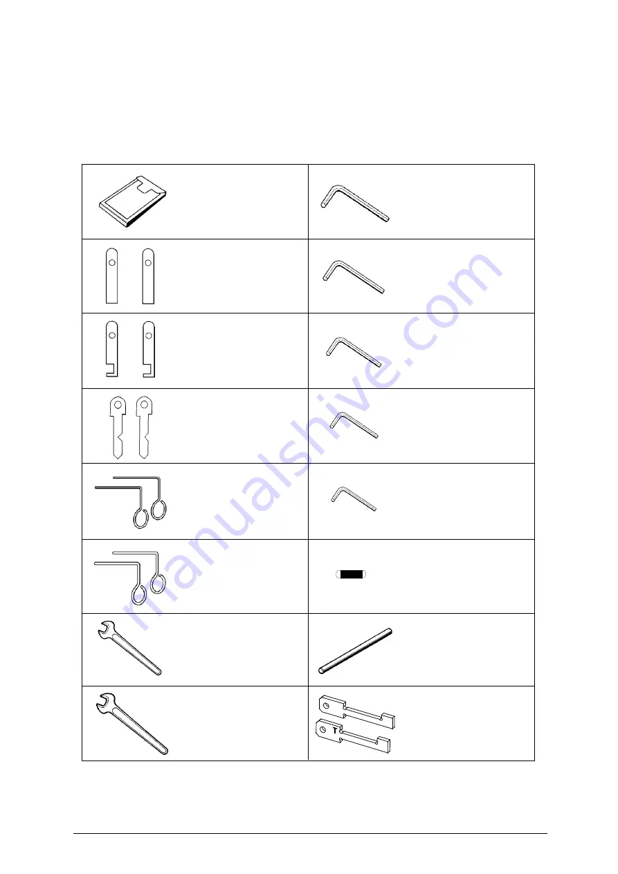
ACCESSORIES PROVIDED

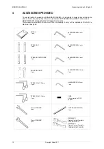
To ensure trouble-free working with the BRAVO MAXIMA, it is advisable to always have certain spare
parts on hand. It is good policy to have a replacement CUTTER, BRUSH and BELT in the tool box.
BRAVO MAXIMA is supplied with a full range of accessories.
The accessories provided by Silca are all that is necessary to carry out the operations for which the
machine is designed.

STEEL PIN 

ø

 1.20 mm 

2 pcs.

CUTTER LOCKING PIN 
1 pcs.

19 mm SPANNER 
1 pcs.

STEEL BAR 
2 pcs.

STEEL BAR WITH NECK 
2 pcs.

ADJUSTING BAR 
2 pcs.

STEEL PIN 

ø

 1.70 mm 

2 pcs.

FUSE 
5 Amps rapid on 230V
(5 pcs.)

POUCH 
1 pcs.

ALLEN WRENCH 2 mm 
1 pcs.

ALLEN WRENCH 2,5 mm 
1 pcs.

ALLEN WRENCH 3 mm 
1 pcs.

ALLEN WRENCH 4 mm 
1 pcs.

ALLEN WRENCH 5 mm 
1 pcs.

10 mm SPANNER 
1 pcs.

D927403ZR
Electric Contact Template 
CUTTER SIDE (C)

D927927ZR
Electric Contact Template 
TRACER POINT SIDE (T)

C

Содержание Bravo Maxima II

Страница 1: ...Operating manual D432446XA vers 5 0 EN...

Страница 2: ...ghts reserved No part of this publication may be reproduced or used in any form or by any means photocopying microfilm or other without the written permission of SILCA S p A Edition April 2011 Printed...

Страница 3: ...ric contact 16 6 CUTTING OPERATIONS 18 6 1 Key cutting 18 6 2 Cutting cruciform keys with 3 fins 19 7 CLEANING AND MAINTENANCE 21 7 1 Preparing for maintenance 21 7 2 Replacing the cutting tool 21 7 3...

Страница 4: ......

Страница 5: ...of the manual are divided into sections relating to Transport and handling Ch 1 Description of machine and safety devices Ch 2 3 4 Proper use of machine Ch 5 6 Cleaning and Maintenance Ch 7 TECHNICAL...

Страница 6: ...It is therefore indispensable to read the operating manual carefully in order to make the best use of the BRAVO MAXIMA and benefit from its potential Instructions manual The instructions manual provi...

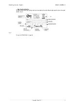
Страница 7: ...English BRAVO MAXIMA II Copyright Silca 2011 3 Machine Identification The BRAVO MAXIMA key cutting machine is provided with an identification label which shows the serial number fig 2 Fig 2 see ch 8...

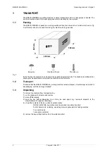
Страница 8: ...chine and all its parts 1 2 Transport To ensure that the BRAVO MAXIMA key cutting machine remains integral it must always be moved in its packaging with the carriage released 1 3 Unpacking To remove t...

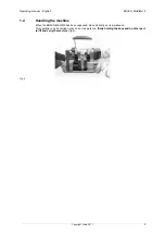
Страница 9: ...ilca 2011 5 1 4 Handling the machine When the BRAVO MAXIMA has been unpacked place it directly on its workbench This operation can be carried out by one or two persons firmly holding the base and no o...

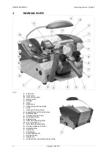
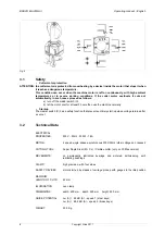
Страница 10: ...ing screw J1 support tracer point locking screw K calibration tabs L carriage movement lever M brush push button N chippings tray O tracer point regulating knob O1 zero registration nut P motor start...

Страница 11: ...ptying and cleaning CUTTING UNIT The cutting unit contains the actual working parts of the BRAVO MAXIMA key cutting machine which operate together to cut and finish keys read from the originals The wo...

Страница 12: ...ormally Start up The master switch C has a safety function that prevents untimely start up when voltage returns after a cut out 3 2 Technical Data ELECTRICAL PROPERTIES 230V 50Hz 300W 1 8A MOTOR 2 spe...

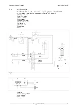
Страница 13: ...s 2 Safe main switch 3 Brush push button 4 Commutator 5 Carriage microswitch 6 Cutter motor condenser 7 Lamp reactor 8 Terminal board 9 Neon lamp 10 Motor Fig 7 11 Display 12 Lithium battery CR2032 13...

Страница 14: ...rovided by Silca are all that is necessary to carry out the operations for which the machine is designed STEEL PIN 1 20 mm 2 pcs CUTTER LOCKING PIN 1 pcs 19 mm SPANNER 1 pcs STEEL BAR 2 pcs STEEL BAR...

Страница 15: ...ot suffered any damage 5 2 Environmental conditions To ensure that the best use is made of the BRAVO MAXIMA key cutting machine certain parameters must be borne in mind damp badly ventilated sites sho...

Страница 16: ...he separately packed parts must be installed on the BRAVO MAXIMA key cutting machine by the purchaser as follows Connection wire Connect the supply wire to the inlet on the back of the machine 5 7 Con...

Страница 17: ...no longer be altered because such a big adjustment is not allowed MODE key activates the Electric contact ch 5 11 Gauging by electric contact When this key is pressed with display on one of the follow...

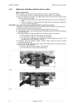
Страница 18: ...drum R towards you away from you to return to the ideal position c Press the I O key on the display in order to turn it on d Press the MODE key the display will show the word OFF no contact ATTENTION...

Страница 19: ...Press the I O key on the display in order to turn it on d Press the MODE key the display will show the word OFF no contact ATTENTION the carriage will be released only if the callipers are in the ide...

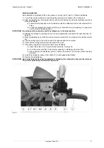
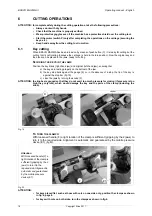
Страница 20: ...button Q right down fig 16 4 Raise the carriage and take up to the cutting tool 5 Take the flat part of the key into contact with the cutting tool and tracer point fig 17 6 Turn the cutting tool by ha...

Страница 21: ...carriage by lowering the knob V and pressing the push button Q right down fig 16 page 16 4 Move the adjusting key so that the notch comes into contact with the cutting tool A and tracer point B 5 Turn...

Страница 22: ...that a the keys are resting properly on the bottom of the jaw b the key stop butts against the gauge K or in the absence of a stop the tip of the key is against the stop bar fig 19 c close the jaws b...

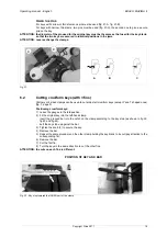
Страница 23: ...an be used to cut almost all cruciform keys except Y and T shaped ones fig 7 page 9 Positioning cruciform keys 1 Leave the gauges in the idle position 2 Fit the original key into the left hand clamp i...

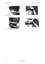
Страница 24: ...BRAVO MAXIMA II Operating manual English 20 Copyright Silca 2011 Fig 23 Key stop UP Fig 24 Key stop DOWN...

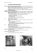
Страница 25: ...rvicing with the machine switched on always remove the mains plug follow all the instructions in the manual to the letter use original spare parts always check that screws and nuts are properly tighte...

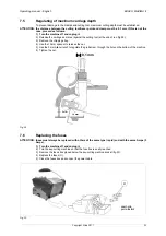
Страница 26: ...se the Allen wrench to loosen the screw holding the brush in place 4 Replace the brush and tighten the screw with the Allen wrench 5 Remove the locking pin Fig 27 7 4 Replacing the tracer point To rep...

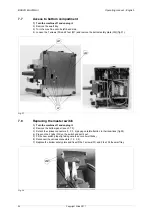
Страница 27: ...fig 29 3 Remove the chippings tray 4 Use the 10 mm spanner to release the nut 5 Use the 3 mm Allen wrench to regulate the grub screw through the hole on the bottom of the machine 6 Tighten the nut Fi...

Страница 28: ...Fig 31 7 8 Replacing the master switch 1 Turn the machine off and unplug it 2 Remove the bottom panel see ch 7 7 3 Detach the various connectors 1 2 3 4 paying careful attention to their positions fig...

Страница 29: ...hem to the new one paying attention to their positions 5 Replace the cap Z2 on the new condenser 6 Replace the bottom safety plate fix with the 7 screws W and 2 feet fig 31 page 24 Fit the swarf tray...

Страница 30: ...4 Loosen the nut Q1 and remove the microswitch fig 35 5 Detach the connectors 1 2 and 3 paying attention to their positions 6 Fit the new microswitch into the seat of the previous one and secure with...

Страница 31: ...rews W and 2 feet W1 and remove the bottom safety plate W2 fig 31 pag 24 6 Pull the commutator C3 downwards and disconnect the wires from their connections in order to remove fig 37 Pay attention to t...

Страница 32: ...ay bolts U2 fig 40 and remove 8 Loosen the screw U3 on the left hand cover fig 40 9 Raise the left hand cover to gain access to the switches 10 Remove the connectors 1 2 3 4 paying attention to their...

Страница 33: ...crew nut U4 to lower the belt tightening pulley remove the existing belt turn the bigger pulley manually exerting a little pressure on the belt on the motor pulley and take out of its seat fit the new...

Страница 34: ...off the motor pulley 12 Loosen the 4 fixing screws on the motor fig 44 and remove paying attention to the wire 13 Loosen the grub screw U6 on the motor pulley fig 45 Remove the pulley and fit to the n...

Страница 35: ...the machine onto its back 11 Loosen the 7 screws W and 2 feet W1 and remove the bottom panel W2 ch 7 7 page 24 12 Loosen the screw N1 on the cam N2 fig 50 page 32 and pull the cam to the right to rem...

Страница 36: ...BRAVO MAXIMA II Operating manual English 32 Copyright Silca 2011 Fig 48 Fig 49 Fig 50 Fig 51 D2 D3 N N2 N1 N3 Q2 Q1...

Страница 37: ...ole on the inside 7 Replace the top part of the display after connecting the wire X3 to the connector inserting it from the front and pushing towards the back 8 Tighten the screw X1 to secure the top...

Страница 38: ...e equipment placed on the market before 31 December 2010 at the end of its useful life and replace it with an equivalent product designed for the same use In this latter case the user may ask the manu...

Страница 39: ...ecial Service Centres recommended by Silca On the back cover of this manual is a list of the manufacturer s addresses listed below are the addresses of specialised Service Centres 9 1 How to request s...

Страница 40: ...ives European Union DIRECTIVE 2006 42 CE Machines and with the EN 292 1 EN 292 2 Standards European Union DIRECTIVE 2004 108 CE Electromagnetic Compatibility and with the EN 55014 1 2000 A1 2001 EN 61...

Страница 41: ...ves European Union DIRECTIVE 2006 42 CE Machines and with the EN 292 1 EN 292 2 Standards European Union DIRECTIVE 2004 108 CE Electromagnetic Compatibility and with the EN 55014 1 2000 A1 2001 EN 610...

Страница 42: ...SILCA S p A Via Podgora 20 Z I 31029 VITTORIO VENETO TV Tel 0438 9136 Fax 0438 913800 E mail silca silca it www silca biz Members of the Kaba Group...

Отзывы: