(4) Slide the head unit terminal cable into the
slit provided on the head carrier.
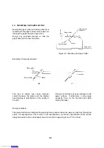
Next, slide the head along the guide of the
head carrier until it touches the guide (see
Figure 8-17).
C
Head
Guide
Head carrier frame
Figure 8-17 Sliding the Head along the Guide
of the Head Carrier
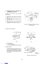
(5) Latch the flexible cable plate to the claws of
the head and push it down until engages
with the dowel on the head carrier.
Claw
Dowel
Head carrier frame
Figure 8-18 Pushing the Flexible Cable Plate
(6) Insert the flexible cable into the cable support of the flexible cable plate with care not to bend the
heat compressor of the head unit (see figure 8-19).
Flexible lead wire
Cable support portion
Home switch
Figure 8-19 Inserting the Flexible Cable
(7) Return the head carrier to the home position (home switch side).
8-11
Downloaded from
Downloaded from
Downloaded from
Downloaded from
Downloaded from
Downloaded from
Downloaded from
Downloaded from
Downloaded from
Downloaded from
Downloaded from
Downloaded from
Downloaded from
Downloaded from
Downloaded from
Downloaded from
Downloaded from
Downloaded from
Downloaded from
Downloaded from
Downloaded from
Downloaded from
Downloaded from
Downloaded from
Downloaded from
Downloaded from
Downloaded from
Downloaded from
Downloaded from
Downloaded from
Downloaded from
Downloaded from
Downloaded from
Downloaded from
Downloaded from
Downloaded from
Downloaded from
Downloaded from
Downloaded from
Downloaded from
Downloaded from
Downloaded from
Downloaded from
Downloaded from
Downloaded from
Downloaded from
Downloaded from
Downloaded from
Downloaded from
Downloaded from
Downloaded from
Downloaded from


