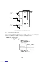
2.6.3 Head Activation Pulse Width
To ensure high quality printing with the MTP Series, the thermal head activation pulse width must be set
according to the head drive voltage and the head resistance.
Pulse width calculation formula
V
E
R
t
2
•
=
t: Pulse width for applying rated energy (ms)
R: Head resistance (
Ω
)
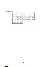
B head
G head
A rank
15.3
Ω
17.6
Ω
B rank
14.0
Ω
16.0
Ω
C rank
12.7
Ω
14.4
Ω
E: Applied energy (mJ)
V: FPC terminal volatge (V)
Note:
Procedure for pulse width adjustment
(1) Minimize pulse width.
(2) Activate the thermal head with a checked pattern.
(3) Measure the head terminal voltage by using a synchroscope.
(4) Gradually adjust applied pulse width, which is calculated by using
the pulse width calculation formula.
2-12
Downloaded from
Downloaded from
Downloaded from
Downloaded from
Downloaded from
Downloaded from
Downloaded from
Downloaded from
Downloaded from
Downloaded from
Downloaded from
Downloaded from
Downloaded from
Downloaded from
Downloaded from
Downloaded from
Downloaded from
Downloaded from
Downloaded from
Downloaded from


