CANOPY
MOUNT SCREWS
(2 REQD)
CANOPY PLATE
(SEE FIG 1 FOR MOUNT)
POWER MODULE
MOUNT SCREWS
#8-32 (2 REQD)
POWER MODULE
MOUNT SCREWS
#8-32 (2 REQD)
-3-
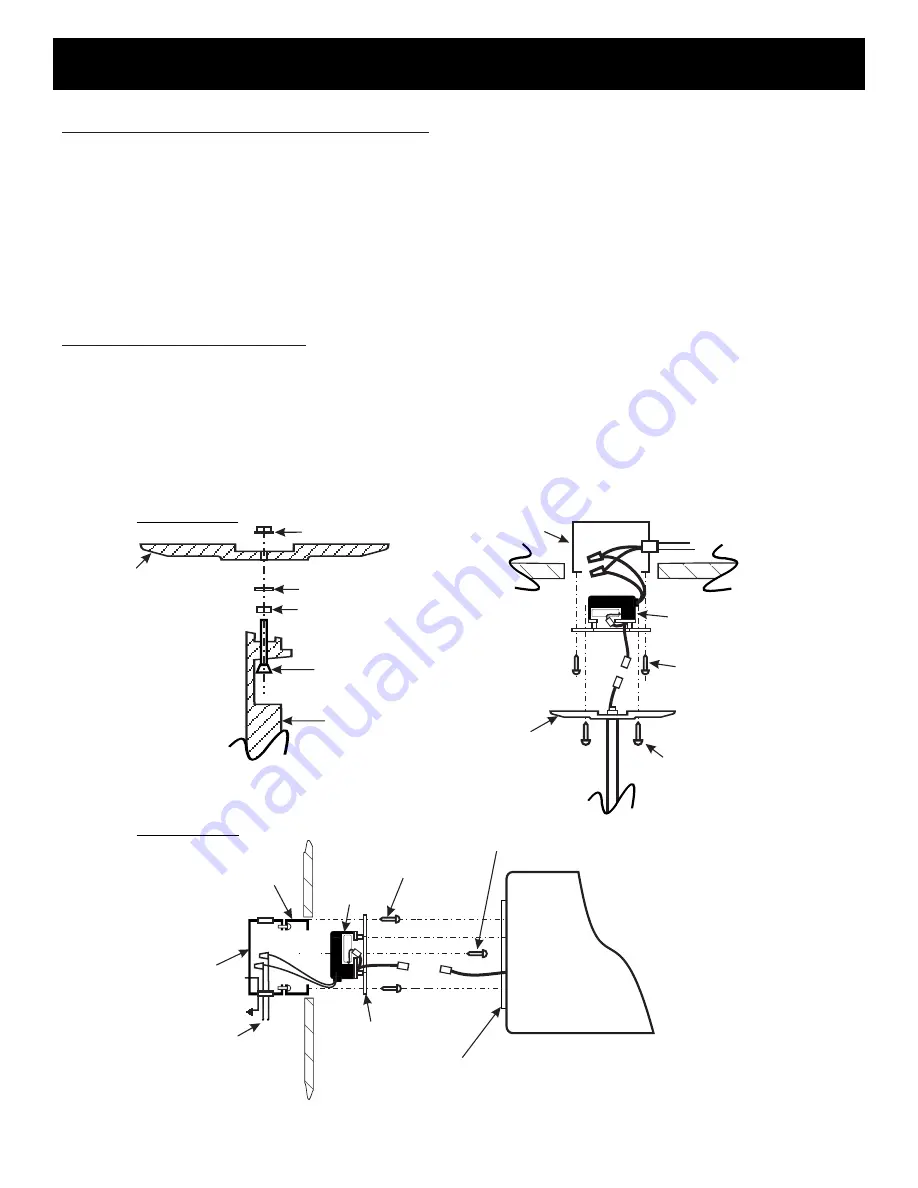
CANOPY MOUNT
SCREWS
(2 REQD)
TOP OR END MOUNT
1
.
Follow WALL MOUNT steps 1-3.
2. For battery backup models, connect 2-pin polarized battery plug.
3. See Fig.1 and 2 below. Route LED connector through slot in top of housing and through canopy.
Insert 6-32 X 3/4" flat head screws into housing and lock down two nuts firmly.
Run flat washers on screws, position canopy, and firmly tighten two lock nuts as shown.
4. Raise sign to J-box, insert excess wiring and plug into center cavity and secure sign assembly with
2 #8-32 color- matched screws supplied.
CHEVRON ARROW SELECTION
1
.
With backplate removed, place sign face on scratch- free surface.
2.Remove four #8-32 screws and detach two corner brackets and one lower bracket. Retain all
screws.
3. Remove lens diffuser and place on scratch- free surface. LED panel and test panel assembly
(in battery backup models only) can be left in place.
4. Place sign face down on raised wooden blocks (or other scratch- free surface), and carefully knock out
selected chevron with hammer and small punch.
5. Place upper edge of lens diffuser against flexible spacers, compress spacers slightly and lower bottom
edge of diffuser into place next to LEDs. Replace three brackets and continue with installation
J- BOX
CANOPY PLATE
POWER MODULE
#6-32 LOCKNUT (2 REQD.)
#6 FLAT WASHER (2 REQD.)
#6-32 SMALL PATTERN
NUT ( 2 REQD)
#6-32 X 3/4" SCREW,
FLAT HD (2 REQD.)
SIGN HOUSING
CANOPY
TOP MOUNT
END MOUNT
AC POWER INPUT
120/277 VAC
CEILING
FIG 1
FIG 2
POWER
MODULE
ADAPTOR PLATE
1 1/2" SQ. EXTENSION
AC POWER
INPUT
120/277 VAC
GRD
J- BOX
W
ALL
Series RPROBB & RPROAC
Rapier Open Face Die Cast LED System
Battery Backup & AC Models
03.15.03


