


7
of 7-1/8".
Consequently you will have to put a 1-3/16" thick
spacer (not supplied) between the firewall and the backplate of the
FPE engine to achieve the proper 7-1/8" distance. Sig has a set
of laser cut plywood spacers specifically for the FPE 3.2 gas
engine. They are part # SIGSH803 (2 spacers per package, so
you will need three packages with a total of five spacers needed to
achieve the 1-3/6" total spacers). You will also need 10-32 x 2"
socket-head bolts and 10-32 blind nuts (not supplied).
b. Position one of
the spacers on the front
of the firewall, carefully
aligning it with the
horizontal and vertical
thrust lines as shown in
the photo and tack glue
in place with thin CA.
Mark the mounting bolt
hole locations on the
firewall with a pencil
and then drill holes
completely through the
firewall.
c.
Install the
10-32 blind nuts by
using a 10-32 bolt, flat
washers, and Allen
Wrench.
Pull the blind
nuts into the rear of the
firewall by tightening the
10-32 bolt with the Allen
Wrench until the blind
nuts are properly seated
and epoxy glue the blind
nuts in place.
d. Mount the engine and additional spacers in onto the front
of the firewall with the 10-32 bolts.
MOUNTING THE COWL:
❑
15) Before mounting the cowling, carefully inspect its inside
rear edges. Use sandpaper to smooth the inside rear surface of
the cowl, making it free of any bumps or ragged edges that may
scratch or dent the fuselage when pressed in place. Also, make
sure the six mounting holes in the sides of the cowl are open and
free of any debris. In addition, remove the muffler, carburetor, and
the spark plug form the engine.
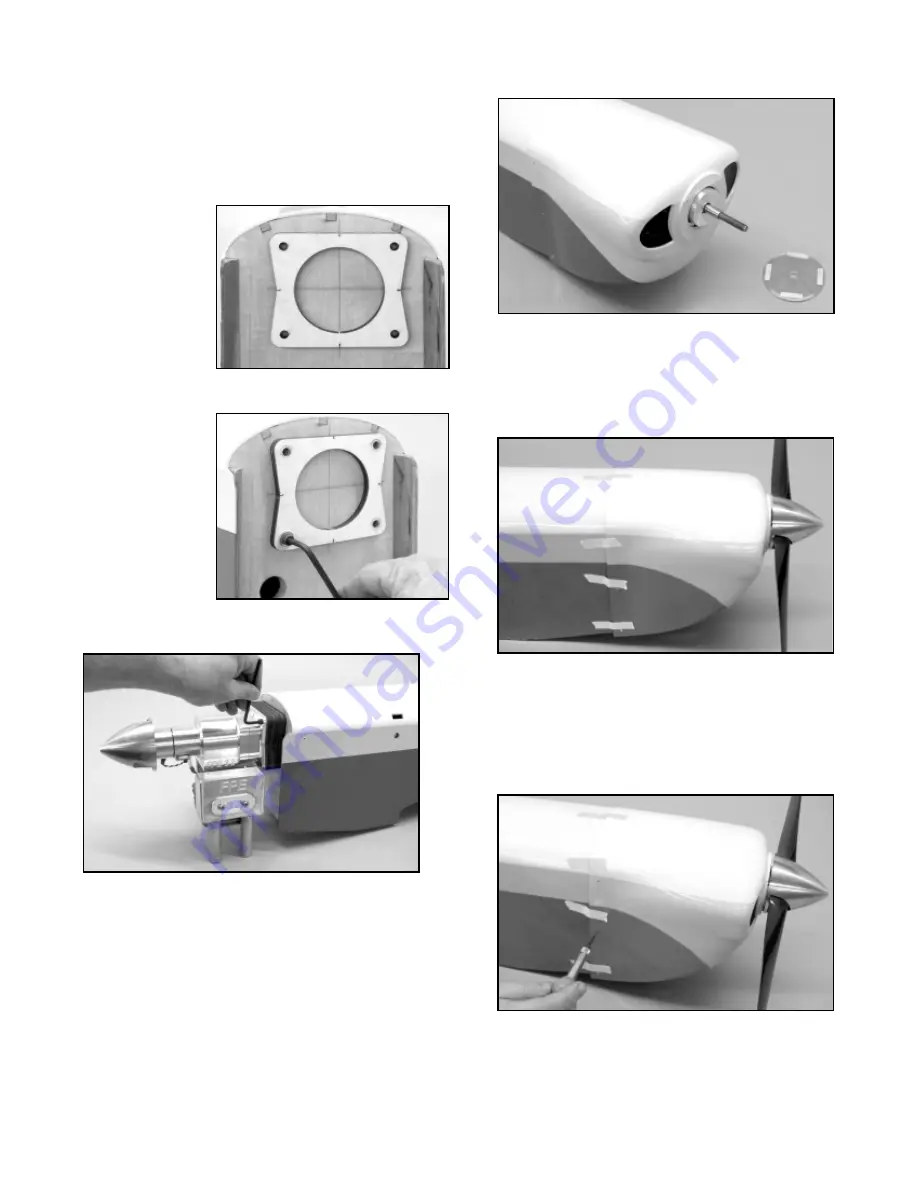
a. Slide the cowl over the engine and the fuselage until it is
roughly in place, making sure that the drive washer on the engine
extends through the opening in the cowl. A minimum of 1/16"
clearance is required between the spinner backplate and the nose
ring on the cowl. Tack-glue four small pieces of 1/16" x 1/4" balsa
to the back of the spinner backplate to act like spacers. Install the
spinner backplate, propeller, and spinner on the engine and
securely tighten in place.
b. Carefully position the cowl on the fuselage making sure
that the spinner is centered on the nose ring of the cowl and
touching the balsa scraps on the spinner backplate. Also use and
the paint stripes on the fuselage and the cowling to help achieve
proper alignment. When satisfied, hold the cowl in place with
strips of masking tape.
c. Using a 3/64" (or #56) dia. drill bit, drill pilot holes in the
fuselage, centered in each of the six pre-drilled holes in the cowl.
Securely mount the cowl in place with the 6 PWA 2.6 x 8mm (.375)
screws that have been provided. Double check your work one
more time to make sure that the cowl is bolted on in the correct
location and is properly aligned. Then remove the cowling from the
fuselage.
d. For most engine installations, there is more than an
adequate amount of openings provided in the cowling for cooling
air to enter and exit. A rule of thumb is that the exit area must be
equal to or larger than cooling air inlet. There must be at least 1/8"
of clearance between the cowling and any accessory such as
muffler and/or carburetor. In these pictures showing the FPE 3.2