SIG P-51B Mustang Скачать руководство пользователя страница 20

19

6) Make sure you can get to your engine’s main needle valve

for on-field adjustments. In most cases this will probably require
making an extension to get the needle valve to exit the cowling.
The main needle valve of most modern engines will have a hole in
the end and a set screw to accept a homemade music wire needle
valve extension. Our Saito 1.00 needle valve has this feature, with
a center hole just large enough to accept a 5/64” dia. (.078”) music
wire needle valve extension. Here’’s the step-by-step method we
used to make a simple neat needle valve extension for our Saito
1.00, and to figure out where it will exit the cowling.

First, remove the cowl. Cut a 2” long piece of 5/64” dia. music wire
and deburr the ends. Insert one end of the wire fully into the hole
in the end of the needle valve and tighten the set screw. Screw the
needle valve all the way into the carburetor. Lay a straight edge
against the side of the fuselage at the nose, intersection the piece
of wire. Mark this point on the wire with a marker pen. Remove
the needle valve from the engine and remove the wire extension
from the needle valve. Cut the wire to length at the mark just
made. Sharpen the end of the wire to a sharp, tapered point using
a bench grinder or a Dremel

®

Tool.

Reinstall the wire back in the needle valve, with the blunt end in the
needle valve and the sharpened end exposed. Screw the needle
valve fully back into the carburetor. Mount the cowling on the 
fuselage. From the front of the cowling, use a pair of hemostats to
begin turning the needle valve out of the caburetor. As the needle
valve is turned, the sharpened end of the wire will come into 
contact with the inside surface of the cowl. Continue turning the
needle valve until it is firmly pressed against the cowl. Place a pad
of paper over the cowl at the location of the sharpened wire point
and lightly tap the paper pad with a small hammer or block of 
hardwood. Removing the pad, you should see a small dimple on
the outside of the cowl.

Remove the cowl and use a 3/32” dia. (.093”) bit to drill a hole
through the cowl at the dimple mark. Remove the needle valve
from the engine, and then remove and disgard the sharpened
piece of wire. Cut a new 3” long piece of 5/64” dia. music wire and
deburr the ends. Grind a small flat spot, about 3/32” long, on one
end of the music wire. Install the new wire in the needle valve,
tightening the set screw against the flat spot.

Remount the cowling on the fuselage. Use a hemostats or long
needle nose pliers to insert the needle valve inside the cowling
through the front opening.

Guide the wire extension through 

the 3/32” hole in the cowl.

Line up the needle valve with the 

carburetor and then screw it full back in. At the outside of the 
cowling, use a fine-tip pen to mark the wire about 1/8” or so away
from the cowl. Once again, take the needle valve out of the cowl.
Use a heavy pliers to bend the wire 90

O

at the mark. Cut off the

bent end of the wire to a length of 1/2” or so, and deburr the end.
Reinstall the needle valve for the final time.

FUEL TANK  INSTALLATION

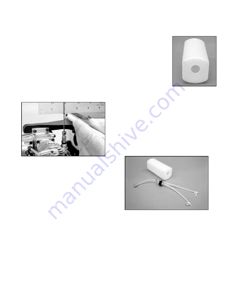
1) Assemble the fuel tank as shown. We recommend that you

plumb the tank with a simple two-line fuel delivery setup. One fuel
line is connected from the fuel tank’s pick-up or "clunk" line to the
engine's carburetor. The second line is the overflow or vent line.
After filling the tank, this same fuel
line is then connected to the
engine's muffler pressure nipple,
providing some manifold pressure
to the tank. Note that the rubber
stopper for the tank has two holes
that go all the way through it. Use
these two holes for the two 
aluminum fuel lines. Also, note that
the correct orientation of the fuel
tank body in the tank compartment
is with its neck "up", in the front
view.

Use the shortest of the three supplied aluminum tubes for the fuel
feed tube. Use the longest of the aluminum tubes for the vent tube.
Gently bend the vent tube upwards to 90

O

, so it will be near the top

of the tank. The fuel pick-up aluminum tubing requires no bending.
Adjust the length of the internal silicone fuel tubing to allow free
movement of the metal clunk pick-up inside the tank.

Install 

the stopper assembly into the neck of the tank and secure by 
tightening the clamp bolt.

Tighten this bolt firmly, causing the 

rubber stopper to compress and expand in the tank's hole, 
creating a secure seal around the neck of the tank.

Cut two 8” or so lengths of silicone fuel tubing (not included), and
slide them over the two exposed aluminum fuel lines. Correctly
identify each of them as "vent" and "carb" and label them with
small pieces of tape. Doing this now avoids any confusion later.

2) Trial fit the tank in place into the front of the fuselage to

familiarize yourself with how it mounts. The front of the tank should
fit through the hole in the firewall. The main body of the tank is 
supported by the contoured hole in the fuselage former. Take the
tank back out of the fuselage.

3) Apply a generous bead of silicone sealer around the neck

of the tank (regular household bathroom type silicone sealer, 
available at most hardware stores, is recommended).

Slide the

tank in place in the fuselage, feeding the two silicone fuel lines and
the neck of the tank through the hole in the firewall. Push the tank
firmly up against the back side of the firewall, compressing the 
silicone sealer to make a good seal.

Note: If your engine mounting bolts are protruding behind the 
firewall, it’s a good idea to take them out and cut them off so they
don’t protrude. If they contact the tank, they might dig into the tank
and cause a leak in the future. Cut them off or use shorter bolts.

Содержание P-51B Mustang

Страница 1: ......

Страница 2: ...ular Y harness were 24 long simply because that s all we could find If your radio manufacturer makes them 12 long that is long enough and will make a neater installation 1 P 51B MUSTANG ARF ASSEMBLY MANUAL INTRODUCTION Congratulations and thank you for your purchase of the SIG P 51B Mustang ARF The unique scale appearance of this seldom seen R C warbird will really stand out at the flying field an...

Страница 3: ...h AeroKote 4 Point Hinges installed in flaps but not glued 1 Aileron Servo Hatch installed with 4 T2 6 x 8 mm PWA Screws 1 Flap Servo Hatch installed with 4 T2 6 x 8 mm PWA Screws 1 Bag 1 Vertical Fin covered with AeroKote 1 Rudder covered with AeroKote 4 CA Hinges installed but not glued 1 Bag 1 Horizontal Stabilizer covered with AeroKote 2 Elevators covered with AeroKote 6 CA Hinges installed bu...

Страница 4: ...e all sealed down and well adhered Then use the heated iron to lightly shrink the wrinkled material do not press on the covering hold the iron right over the surface After the covering is tight you can lightly iron the material down to the wood You can also use a hobby type heat gun to re shrink the covering material but you must be extra careful around the seams This is because a heat gun generat...

Страница 5: ...not be repeated later in the book when those surfaces are hinged You can refer back to this section at that time a The CA hinges supplied have a die cut center slot that can be used to accurately place and center the hinges equally into both the wing panel and the aileron To do this use a business card and pair of scissors to cut four wedges These should be cut wide enough at the top so as to not ...

Страница 6: ...e to use plenty of glue Wipe off any excess glue that oozes out of the joint with an alcohol soaked rag or paper towel Let dry 4 For gluing the two wing panels together we recommend that you use slow drying epoxy glue so you will have plenty of time to get them properly aligned and cleaned up Mix a batch of epoxy large enough to cover both center ribs and the exposed wing joiner Apply the glue gen...

Страница 7: ...acturer s instructions 4 Inside the aileron servo bay opening you will find a short length of wood with a string tied to it The string will be used to pull the aileron servo wire through the wing panel to the center of the wing Gently break the wood piece loose from the wing structure Pull it and the string a few inches out of the servo bay opening Remove the wood from the string and discard it Ti...

Страница 8: ...Repeat for the other mounting block on the hatch f Now you can mount your servo to the hatch Be sure to drill pilot holes in the mounting blocks before screwing the servo in place using the screws that came with the servo 7 Repeat this step to pass the aileron and flap servo wires through the opposite wing panel 5 The aileron and flap servos will be mounted to the back uncovered sides of their res...

Страница 9: ...hen in the flap up g Use your radio system to center the servo and check servo travel Install the servo arm Check to see that the arm does not bind on the slot in the hatch at extremes of travel Note If you have a double sided servo arm cut off the side of the arm that you won t be using so that it cannot bind on the top wing sheeting when the hatch servo are installed in the wing h Repeat steps a...

Страница 10: ...ately 45O Reposition your flap servo arms as necessary to get them in this position Now when the transmitter is set to the down flap position the servo arms should both pull towards the wing leading edge If your down flap motion moves the servo arms towards the flaps instead of towards the wing leading edge then you need to reverse the direction of the flap channel in your transmitter Activate the...

Страница 11: ...s on the axles They may not look like your favorite wheel collars but they really do work Once installed they won t come off a Lay one of the retracts on a sturdy bench with the axle boss resting flat on the bench and the axle itself pointing straight up in the air Push one of the wheel retainer washers onto the axle with the domed side oriented as shown It takes a hard push to get the washer star...

Страница 12: ...ter s servo reversing feature to setup your retract system as described above When you finish the setup put the retract switch and servo in the GEAR UP position and then turn off the radio Mechanically put the landing gear legs in the GEAR UP position Note If you have a problem pushing the washer on the axle by hand with your thumbs find a scrap piece of 1 4 thick plywood or other hardwood and dri...

Страница 13: ...he pushrod connector c Turn your radio on and actuate the retracts to the GEAR DOWN position Observe the operating cycle carefully watching for any binding in the linkage If they operate smoothly cycle the gear several times UP and DOWN Check to see that the retracts reach the end of their stroke and fully lock in the UP and DOWN positions If your retract installation isn t working smoothly study ...

Страница 14: ...peeling the covering off the fuselage where the fairing sits Epoxy Method Hold the Molded Plastic Left Wing Fairing in place on the fuselage Use a fine point felt tip pen to mark the location of the fairing onto the fuselage side Then set the fairing aside and use a sharp 11 hobby knife to cut through the covering material about 1 16 inside the marked line Be very careful to cut the covering mater...

Страница 15: ... make sure that tailwheel wire moves freely in the bracket Also make sure that the steering arm set screw is 14 tight to keep it from coming loose in flight take the set screw out and put a small drop of Locktite on the threads and then tighten it back up b Drill out the holes in the steering arm with a 1 16 dia drill bit c Remove the hatch in the bottom rear of the fuselage that covers the tailwh...

Страница 16: ...back off the airplane and carefully remove the covering material between the lines so there will be a good wood to wood joint between the stab and the fuselage Be very careful not to cut into the balsa wood when removing the covering 15 7 Slow drying epoxy glue is recommended for gluing the stabilizer on the fuselage to allow you plenty of time to get the stab in proper alignment before the glue d...

Страница 17: ... a Attach a 24 long servo extension chord to your elevator servo Put tape around the connection so it can t come loose b Hold the fuselage vertical nose down and feed the extension chord into the fuselage through the servo opening Keep feeding the chord forward towards the front of the fuselage When it s all the way in set the elevator servo in place and mark the mounting holes on the plywood serv...

Страница 18: ...eep the blind nuts from ever coming loose Be careful not to get any glue in the threads of the blind nuts 1 a Set your engine on the engine mounts and move it forward or backward until you measure exactly 5 3 4 from the front of the firewall to the front face of the prop drive washer This is the distance your engine needs to be from the firewall for proper cowl alignment and prop clearance purpose...

Страница 19: ...gine prop shaft Tighten the prop assembly sufficiently to bring the spinner backplate firmly in contact against the engine s prop mounting flange Now check to see that you have at least a 1 16 gap between the back of the spinner backplate and the front of the cowling 1 16 to 1 8 is OK Adjust the final location of the cowling making sure that the spinner backplate is centered at the front and that ...

Страница 20: ...back in At the outside of the cowling use a fine tip pen to mark the wire about 1 8 or so away from the cowl Once again take the needle valve out of the cowl Use a heavy pliers to bend the wire 90O at the mark Cut off the bent end of the wire to a length of 1 2 or so and deburr the end Reinstall the needle valve for the final time FUEL TANK INSTALLATION 1 Assemble the fuel tank as shown We recomme...

Страница 21: ...the rear mark along the top edge of the masking tape Mark this location on the cowl Remove the cowl and drill a 3 32 dia hole through the cowl at the mark just made Remove 4 A 8 mm x 20 mm x 120 mm Balsa Stick approx 5 16 x 3 4 x 4 3 4 is provided to keep the fuel tank in place Install the balsa stick across the back of the tank gluing it to the front of the fuselage former This will keep the tank...

Страница 22: ...back against itself to avoid lifting the covering material Remount the cowling on the fuselage You should now be able to see the center of the fueling valve through the small hole just drilled in the cowl It might be a little off center but this is easily corrected in a moment The Du Bro fueling probe that comes with the valve itself requires a 1 4 hole diameter to fit fully into the valve Use a p...

Страница 23: ...rod tubing to use as an antenna holder Slide the antenna inside the tube stringing it out as straight as possible Then mount the tube in the aft portion of the fuselage sticking it through the holes in the formers Glue the tube securely to the fuselage structure DECAL APPLICATION The decals supplied with your P 51B Mustang are sticky back Mylar with a very aggressive adhesive They are NOT water ac...

Страница 24: ... our prototype MUSTANGS Other brand pilots of the same scale will also work As your experience with the P 51B Mustang increases you can adjust the balance point to suit yourself In general as the balance point is moved aft the airplane will become more responsive and less stable in all axis Some pilots like their models extremely reactive while others like to fly with more smoothness In the end th...

Страница 25: ...rolled flight resuming quickly This is great information to have when set up for your first landing PRE FLIGHT SAFETY CHECK Turn the radio system on and check the function of all the controls Make sure they are moving in the right direction Thousands of R C airplanes have crashed over the years because the servos were moving the wrong way Also make sure all the servos are centered and working perf...

Страница 26: ...necessary sound piloting skills are After landing always remember to hold up elevator when taxiing to keep the tailwheel firmly to the ground Before flying your Mustang a second time double check the airplane carefully for anything that may have come loose become disconnected etc during the first flight Each flight will be even more fun as you get more familiar and comfortable with your Mustang Pl...

Страница 27: ...26 ...

Страница 28: ... that 75 of its crewmembers never completed their 25 missions The US Air Force was on the brink of cancellation of daylight raids until the P 51B Mustang came along Birth of the Mustang In 1940 the embattled British were buying P 40s as fast as Curtiss could build them Needing more fighters they approached North American Aviation to ask if they would build P 40s for them under license from Curtiss...

Страница 29: ...f 440 mph at 30 000 feet and a climb to 20 000 feet required only five minutes and 54 seconds The P 51B was approximately 30 mph faster than the Spitfire with the same engine and faster at high altitude than any other fighter airplane of the time This was a remarkable advance in flight performance The addition of a new 85 gallon fuselage tank gave the P 51B a huge internal gasoline tank capacity a...

Страница 30: ...day pushes Gentile s total to 27 breaking the record of 26 set by Captain Eddie Rickenbacker during World War I On this same day Duane Beeson is brought down by German ground fire while strafing He is captured thus ending the Ace Race Beeson would spend the rest of the war as a POW He scored 22 victories April 8 1944 Scores 3 Fw 190s kills 28 29 and 30 These three kills fill out the final total of...

Страница 31: ...ing than the later bubble topped P 51D P 51B C fighters remained predominant until the middle of 1944 when large numbers of P 51Ds began to arrive Even as late as the last month of the war 1000 out of the 2500 Mustangs serving in the ETO were of the P 51B C variety The last P 51B passed out of service in 1949 Great publicity shot of Don Gentile relaxing on the wing of his legendary P 51B Shangri L...

Страница 32: ...5 000 ft 430 MPH At 30 000 ft 440 MPH Time to Climb to 5 000 ft 1 8 minutes to 10 000 ft 3 6 minutes to 20 000 ft 7 0 minutes Service Ceiling 42 000 ft Range On Internal Fuel 410 Miles With Drop Tanks 1 450 Miles Top Surfaces Olive Drab FS 34087 Bottom Surfaces Neutral Gray FS 36173 Serial No Orange Yellow FS 33538 Call Letters White Spinner Nose Red Aircraft P 51B 7 NA Serial No 43 6913 Call Lett...

Отзывы: