background image

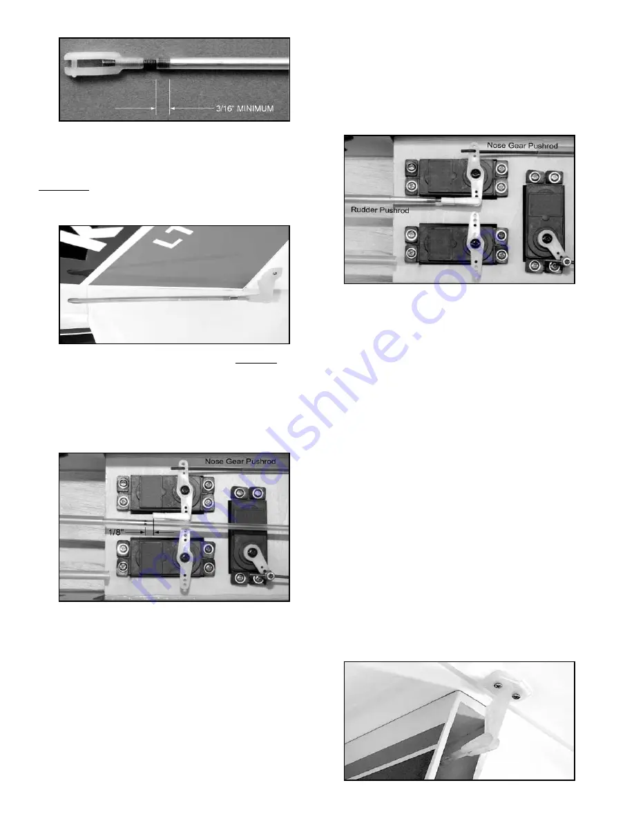
7) From the tail end of the airplane, slide the rudder pushrod
inside the pushrod sleeve that is already in the fuselage. Slide it in
until the nylon R/C Link is even with the rudder control horn. Pry
open the R/C link and clip it into the outermost hole of the rudder
control horn. Now reach into the fuselage and try operating the
rudder from the servo end of the pushrod. It should work smooth
and easy. If not, figure out why and fix it now before proceeding.

8) a) Now clip another R/C Link into the rudder servo arm - on the
side of the servo opposite the nose gear pushrod.

b) Set the rudder in neutral position.
c) Mark the inner pushrod tube exactly 1/8" from the end of the

R/C Link.

d) Unhook the R/C Link from the rudder horn and slide the

pushrod tube back out of the airplane. Cut off the tube at the mark
just made, using a sharp razor blade or modeling knife.

9) Cut a 10" Threaded Steel Rod to 7" overall length. Coat the
plain portion of the 7” rod with a very thin layer of epoxy glue.
Immediately slide the plain end of the rod inside the servo end of
the rudder pushrod tube. Screw at least 3/16" of threads into the
tubing. Wipe off any excess epoxy glue and let dry.

10) Slide the rudder pushrod back inside the sleeve in the fuselage
and clip the rear R/C Link back onto the elevator horn. At the 
servor end of the pushrod, screw a nylon R/C link halfway onto the
exposed threads of the steel rod. Then clip that R/C link into the
rudder servo arm.

11) Plug the rudder servo into the receiver and test the operation
of the rudder. If you sense any binding in the rudder movement,
find the cause and fix it now. With full right and left movement of 

the transmitter's rudder control stick, the rudder should move
approximately 1" right and 1" left.

NOTE: If you are not getting the correct amount of rudder travel, try
using your transmitter’s “End Point Adjustment” feature to dial in
the proper amount. Also fine tune the overall length of the rudder
pushrod, by screwing one or both of the nylon R/C Links further in
or out, until the rudder is neutral when the transmitter is neutral.

ELEVATOR PUSHROD
Locate the following parts from the kit contents:

(1) Nylon Control Horn

(1) Nylon Control Horn Retainer

(2) M2 x 12mm Bolts, for control horn

(1) 1/8” O.D. x 38” Nylon Pushrod Tube

(2) 2-56 x 10” Threaded Rods

(2) Nylon R/C Links

1) Mount a Nylon Control Horn on the bottom of the Elevator using
two M2 x 12mm Bolts. Make sure the Elevator Horn is in the 
center of the tail opening so that the R/C link won't hit the fuse
sides.

2) Cut another 10" Threaded Steel Rod to 7" overall length. Coat
all of the plain portion of the 7” rod with a very thin layer of epoxy
glue, and then proceed immediately to the next step before the
glue dries.

3) Slide the glue coated end of the 7" long threaded rod inside the
1/8” O.D. x 38” Nylon Pushrod Tube, all the way up to the beginning
of the threads. Then screw at least 3/16" of threads inside the 
tubing. Wipe off any excess epoxy glue. After the glue dries, screw
a nylon R/C link halfway onto the exposed threads of the steel rod.

4) Slide the elevator pushrod inside the pushrod sleeve that is
already in the fuselage. Slide it in until the nylon R/C Link can be
snapped into the bottom hole of the elevator control horn. Then
reach into the fuselage and try operating the elevator from the
servo end of the pushrod. It should work smooth and easy. If not,
figure out why and fix it now before proceeding.

20

Содержание KADET LT-40 EG

Страница 1: ...he model before each flight to make sure it is completely airworthy 3 To always fly your model in a safe approved location away from populated areas 4 To always fly your model in a safe manner Your first test flights should be made with the assistance of an experienced R C flyer LIMIT OF LIABILITY SIG Mfg Co Inc guarantees this kit to be free from defects in material and workmanship at the date of...

Страница 2: ...fore you will need to find a qualified R C flight instructor to test fly the airplane and teach you how to fly it If this is your first radio control model airplane DO NOT attempt to fly it by yourself without a qualified instructor ARE YOU INSURED The governing body for radio control model airplanes in the United States is the ACADEMY OF MODEL AERONAUTICS sometimes referred to as the AMA While AM...

Страница 3: ... 4500mAh LITHIUM POLYMER BATTERY PACK With the Maxx Products HC3528 1000 motor we use 3 cell 3S1P 4500mAh or 4 cell 4S1P 4500mAh Li po packs A 3 cell pack 11 1 volts provides flight performance similar to a 40 glow engine A 4 cell pack 14 8 volts provides flight performance similar to a 46 glow engine We find that 4500mAh lipo packs provide between 10 to 15 minutes of flight time depending on prop...

Страница 4: ...4 Please check the contents of your kit box with these diagrams If any parts are missing contact SIG Mfg Co at 641 623 5154 Note Not all parts are shown at same scale ...

Страница 5: ...ar Retaining Straps 4 M3 x 10mm Screws 2 4 5mm I D Plastic Wheel Spacers 2 4 5mm I D Wheel Collars with Set Screws Nose Gear Assembly 1 4mm dia Nose Gear Wire 1 2 3 4 Dia Nose Wheel 1 Nylon Nose Gear Steering Bearing 1 Nylon Nose Gear Steering Arm with Set Screw 4 M3 x 14mm Mounting Bolts 4 M3 Flat Washers 1 4mm I D Plastic Wheel Spacer 1 4mm I D Wheel Collar with Set Screw Spinner Assembly 1 2 di...

Страница 6: ...step is to set the iron to the correct temperature This is critical for achieving a good result The iron should be set to about 220O F 250O F 104O C 121O C as measured on the bottom of the iron using a thermometer If you do not have a thermometer you can find the correct temperature by trial and error Set your iron to a medium setting Glide the iron over some of the covering that is over over soli...

Страница 7: ...ue oozes out of the slot when you push the Wing Joiner in 4 Apply a liberal amount of Epoxy Glue to the end ribs of BOTH Wing Panels and to the exposed end of the Wing Joiner 5 Slide the other Wing Panel onto the Wing Joiners and up tight against the first panel Firmly press the Wing Panels together and wipe off any excess Epoxy Glue with a paper towel and rubbing alcohol Make sure the two Wing Pa...

Страница 8: ...leaners Then peel the paper backing sheet completely off the decal being careful not to let the sticky side double over and adhere to itself Place the decal onto the wet surface of the model The soapy water solution will keep the decal from actually sticking to the model until you have had time to shift it around into exact position Once you have it in position use a piece of stiff cardboard or sh...

Страница 9: ...ly onto the Fuselage with slow drying Epoxy Glue Mix the Epoxy and spread a generous coat evenly on the area of the Fuselage where the Stabilizer goes Remount the Stabilizer onto the Fuselage using the edges of the cutaway covering on the bottom to get the Stabilizer back into correct alignment on the Fuselage Press the Stabilizer down firmly and pin it in correct position Use a paper towel and ru...

Страница 10: ...ush the wires down tight into the groove NOTE If the wire doesn t want to fit completely down into the groove of the landing gear block it may be necessary to remove a little material from the inside edge of the hole to allow for the radius of the bend in the wire Do this with a round file or modeling knife 4 Place the two nylon Landing Gear Straps over the Main Gear Wires as shown in the picture ...

Страница 11: ...do using a long 1 4 dia drill bit to drill a new hole aligned with the engine s throttle arm through the firewall and through the second fuel tank support former behind it Locate the following parts from the kit contents 1 Right Glass Filled Engine Mount 1 Left Glass Filled Engine Mount 4 M3 x 20mm Phillips Head Bolts for mounts 4 M3 Flat Metal Washers for mounts 4 4 40 x 1 Slotted Bolts for engin...

Страница 12: ...e Spinner in place and check to see if the Propeller clears the openings If necessary loosen the Prop Nut reposition the Propeller re tighten the Prop Nut and then check again Adjust as many times as necessary to make sure that the Propeller comes out the center of the openings THE PROPELLER MUST NOT TOUCH THE SPINNER When you have it in the right position tighten the Prop Nut 4 Install the Spinne...

Страница 13: ... the cap of the tank If it s leaking tighten the screw in the cap a little at a time until the leaking stops 8 Trial fit the tank in place inside the fuselage to familiarize yourself with how it mounts The neck of the tank should fit through the hole in the firewall 9 Apply a generous bead of silicone sealer around the neck of the tank regular household bathroom type silicone sealer available at m...

Страница 14: ...chieve access to the engine s needle valve and to the fuel line tubing at the carb NOTE A Dremel tool or similar power tool with a coarse grit sanding drum is without a doubt the best tool to use for removing the cowling material quickly easily and accurately However if you do not have access to such a power tool you can cut the opening with a drill and a hobby knife First drill a series of almost...

Страница 15: ...the exact location of your engine s carburetor control arm Some arms may be a little closer to the fuselage side while some may be closer to the engine s center line For most 2 stroke 40 46 R C engines it will simply be a matter of increasing or decreasing the angle of these two bends to change the total distance of the offset in the wire If you need to change the bends change both bends the same ...

Страница 16: ...S If you are using a different brand electric motor or motor mount you need to make sure that the combination you select can provide exactly 4 1 2 distance from the front of the prop adaptor to the front of the firewall i e back of the mount 4 1 2 is the distance needed for the cowling to fit properly 1 There are four sets of cross hairs etched on the front of the plywood firewall to mark the loca...

Страница 17: ...s sticky back 7 Cut 3 small pieces of 3 4 wide hook and loop tape not supplied and stick them on the battery compartment floor where shown in the following photo Put a long strip of the mating tape on the bottom of each of your battery packs This will keep your battery pack from shifing position in flight 8 Cut two 9 long pieces of 3 4 wide hook and loop strap material not supplied Install the two...

Страница 18: ...switch CAUTION Make sure the opening for the switch s on off lever is just slightly bigger than the lever so that the switch will operate without catching or binding on the wood INSTALL THE ELEVATOR RUDDER SERVOS Mount your elevator and rudder servos in the plywood Servo Tray using the screws and rubber grommets that came with your radio system Be sure to orient the servos in the tray as shown her...

Страница 19: ...lon Control Horn in position on the left side of the rudder and mark the location of the mounting holes Drill pilot holes through the rudder with a 1 16 dia drill bit turn the bit with your fingers or a pin vise a power drill is not necessary 2 Mount the Control Horn onto the rudder with the Retainer Plate and Bolts 3 Cut one of the 10 Threaded Rods to 5 overall length Cut the plain end of the rod...

Страница 20: ...ow With full right and left movement of the transmitter s rudder control stick the rudder should move approximately 1 right and 1 left NOTE If you are not getting the correct amount of rudder travel try using your transmitter s End Point Adjustment feature to dial in the proper amount Also fine tune the overall length of the rudder pushrod by screwing one or both of the nylon R C Links further in ...

Страница 21: ...ten the servo mounting screws to the point where they compress the rubber grommets too far 2 The aileron pushrods are made from two 10 Threaded Steel Rods Screw a nylon R C Link halfway onto the threaded end of each rod Then clip the R C Links into the holes in the Nylon Aileron Connectors and line up the pushrods with the servo arms 3 Tape the ailerons in neutral position the bottom of the ailero...

Страница 22: ... receiver seems loose in the nose of the model pack additional pieces of foam rubber around it to make sure it cannot move around in flight Make sure the receiver antenna wire is accessible at the back of the receiver free and clear of all the other wires 4 NOTE The following step describes running the antenna outside the airplane along the bottom of the fuselage There are a lot of other ways to h...

Страница 23: ... servos If you can t get your model balanced simply by re locating the battery pack then you will have to purchase lead weights from your hobby dealer and glue them into the tail end of the fuselage If the airplane sits on your fingertips with the tail down it is tail heavy DO NOT ATTEMPT TO FLY IT A tail heavy model is very dangerous and will most likely crash Weight will have to be added to the ...

Страница 24: ...e your brand new airplane in a crash To practically eliminate any chance that your first flight will end in disaster we strongly recommend that you seek the assistance of a competent R C pilot to help you with your first flights An instructor serves two purposes First he will take your model up for its first test flight to make sure it is performing properly before you try to fly it When a brand n...

Отзывы: