


15
THROTTLE PUSHROD
Locate the following parts from the kit contents:
❑
(1) Nylon Outer Pushrod Sleeve (already in the fuselage)
❑
(1) 1/16” dia. x 16” Straight Music Wire Pushrod
❑
(1) Brass Pushrod Connector
❑
(1) Plastic Pushrod Connector Retainer
❑
(1) 4-40 x 1/8” Pushrod Connector Bolt
1) The first step is to install your throttle servo in the fuselage,
using the rubber grommets, eyelets, and screws that came with the
servo. Mount the servo in the front opening in the servo tray,
lengthwise across the fuselage. The servo arm should be towards
the right side of the airplane, as shown in the following pictures.
2) The plastic outer sleeve for the throttle pushrod is already
installed in the fuselage, but not glued. Position the sleeve so that
approximately 1-1/2” sticks out in front of the firewall.
Then
permanently glue the sleeve to the firewall and to the fuselage
former that is in front of the servos.
3) Install a complete Pushrod Connector assembly in the outer
hole of the throttle servo arm (see diagram of Pushrod Connector
on page 4). NOTE: It may be necessary to open up the hole in the
servo arm with a 1/16” drill bit to allow the connector to go in freely.
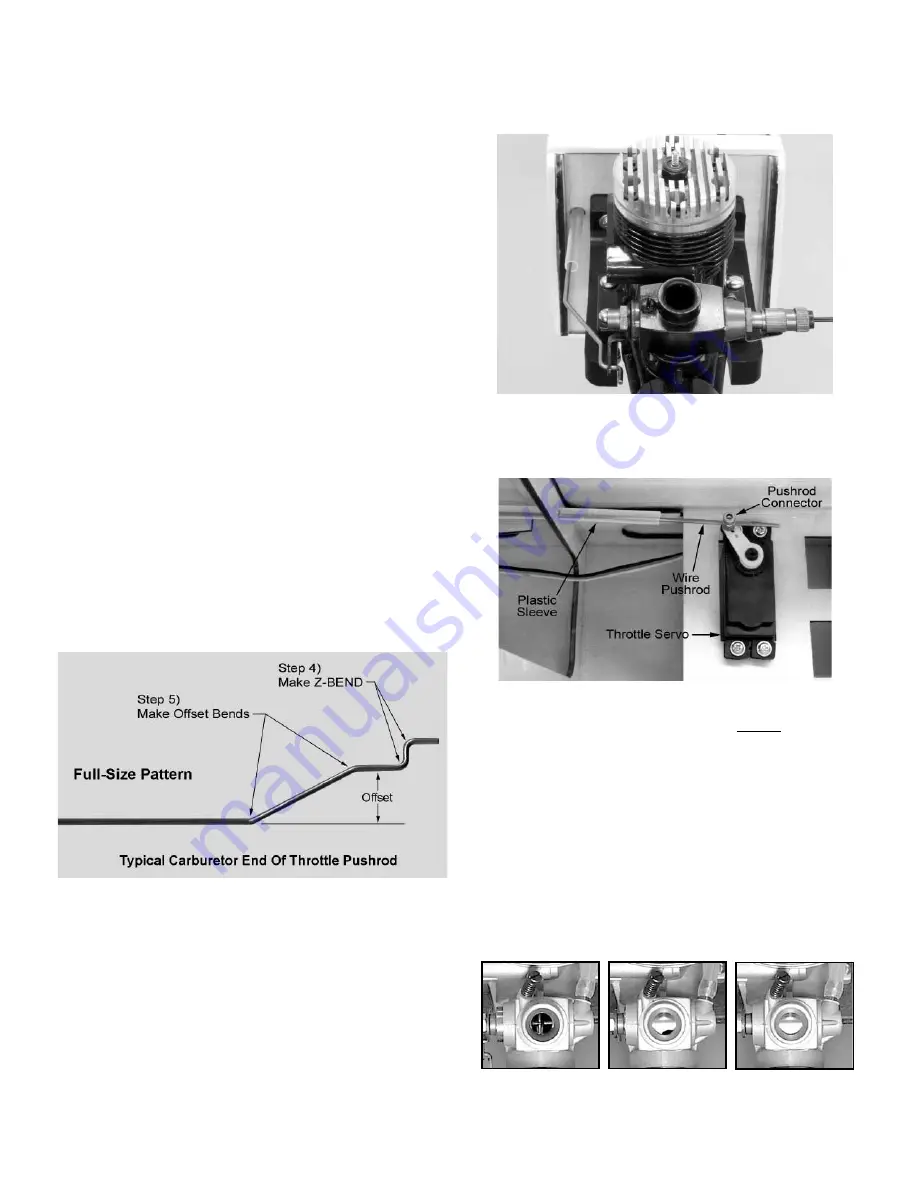
4) A piece of straight Music Wire 1/16” dia. x 16” long is provided
to make the throttle pushrod. Put a “Z-BEND” in one end of the
pushrod (refer to page
__
for instructions on making Z-BENDS in
music wire). This will be the end of the pushrod that hooks up to
the engine’s throttle.
5) Just back from that "Z-BEND" you need to put 2 more bends in
this wire to move the "Z-BEND" over in line with the engine's throt-
tle arm. If you are using a typical .40-.46 size 2-stroke engine, with
a standard carburetor, bend your wire to match the pattern shown
here. It should work in most cases!
NOTE: This offset in the throttle pushrod wire may need to be
slightly different depending upon the exact location of your
engine's carburetor control arm. Some arms may be a little closer
to the fuselage side, while some may be closer to the engine's
center-line. For most 2-stroke .40-.46 R/C engines, it will simply
be a matter of increasing or decreasing the angle of these two
bends to change the total distance of the offset in the wire. If you
need to change the bends, change both bends the same amount,
always keeping the two legs of the wire parallel to each other.
6) Temporarily unbolt the engine/engine mounts from the firewall
so that you can insert the "Z-BEND" into the bottom hole of the
engine's throttle arm. NOTE: You may be need to enlarge the hole
in the throttle arm with a 1/16” bit to accept the Z-BEND.
7) Slide the unbent end of the throttle pushrod wire inside the
plastic outer sleeve as you re-bolt your engine/engine mounts to
the firewall. When the pushrod wire gets to the throttle servo, slide
the end of the wire inside the pushrod connector.
8) Hold the engine’s throttle arm in high throttle position, put the
throttle servo in high throttle position, and then tighten the set
screw in the pushrod connector at the servo.
NOTE: Most 2-stroke R/C engine carburetors will provide high
throttle when the throttle arm is pushed fully forward. Check your
carburetor and confirm the correct direction of travel for "low" and
"high" throttle movement.
9) Plug the throttle servo into your fully charged radio system (see
radio owner’s manual) so you can test the operation of the throttle
pushrod. If your throttle servo is moving in the wrong direction, use
the transmitter’s “servo reversing” feature to change it.
Make
adjustments to the throttle pushrod setup until you can achieve
these results from movement of the transmitter throttle stick and
throttle trim lever:
NOTE: Adjusting carburetor linkage can be a little tricky! If you
have binding, check for an incorrect amount of offset (bend) in the
STICK FORWARD
TRIM FORWARD
HIGH SPEED
STICK BACK
TRIM FORWARD
GOOD IDLE
STICK BACK
TRIM BACK
KILL ENGINE