SIG CAP 231EX Скачать руководство пользователя страница 10

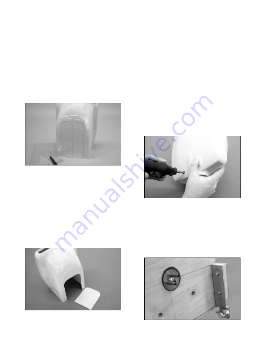
cowl, approximately 3-1/4" in from the outer edge. Stand 
the triangle up against the bottom edge of the cowl, aligned 
with the mark just made. Use the felt marker to draw a 
vertical line up toward the nose about 8" long. Measuring 
from this centerline, make a mark at 2-1/16" to the left of the 
centerline and another at 2-1/16" to the right of the 
centerline.

Again using the triangle and the marks just 

made, draw a straight vertical lines on the cowl from  the 
bottom edge up towards the nose, again about 8" long.
These two outer lines should parallel the centerline.
Measure 7" up from the back edge of the cowl, making 
a mark at one of the outer vertical lines.

Repeat this 

measurement and mark on the other outer vertical line. Use 
a straightedge and marker pen to connect these two marks.
This gives you the area to be cut out from the bottom of the 
cowl. To avoid sharp corners and for a better look, we 
suggest using a circle guide to round the two upper corners 
of this cut out area.

The fiberglass can be cut from the cowl easily, using a 
Dremel® Tool and a large cut-off wheel. Before cutting out 
the cowl opening be sure to wear safety glasses and a 
mask of some kind to avoid inhaling any fiberglass dust.
Carefully cut the fiberglass, using the lines previously 
drawn. If you are careful, you will find that you can get 
fairly close to the lines with the cut-off wheel. The goal is to 
remove most of the material within the lines.

Once the 

piece is cut and removed, exchange the cut-off wheel for a 
sanding drum bit in your Dremel® Tool.

Use the drum 

sander bit to round the upper two corners and to lightly 
clean up any jagged edges. Use 220 sandpaper to clean 
up the edges of the cutout, without sanding the paint. Make 
sure the edges are uniform and free of any loose glass.
Remove all fiberglass dust from the cowl with alcohol and a 
clean cloth.

9) Mount the now trimmed cowl back onto the fuselage, over 

your engine. In this step you will determine the location for 

the hole required for your engine's needle valve to exit the 
cowl. This is easiest done using the penlight mentioned 
earlier in step #1 and fine line marker pen. First find the 
approximate location of where the needle valve will exit by
looking carefully at your engine's carburetor.

Mark that 

location onto the cowl.

Now look a little closer and use the penlight to adjust the 
mark just made from the outside of the cowl. Reposition the 
mark as required to get as close as possible to the actual 
exit location.

Use the Dremel® Tool and a small tipped 

grinding bit to make a small hole (maybe 1/16" in diameter) 
in the cowl, at the exit mark just made. Chances are that 
you were quite close to the actual exit point. Stick a piece 
of music wire into the hole, down to the needle valve hole in 
the carburetor. Carefully observe if the hole needs to be 
repositioned to straighten up the wire, as if it were the 
needle valve. Make another mark on the cowl and again 
use the Dremel® Tool to open the hole just a little towards 
the correct position. In this manner, continue checking and 
adjusting the exit hole until it aligns perfectly with the 
carburetor/needle valve position.

Use the Dremel® Tool 

and tapered bit to open the hole enough to insert and install 
the needle valve in the carb. Be sure the hole has at least 
3/32" clearance around the needle valve to avoid contact.

10) You must be able to fuel and de-fuel your CAP 

conveniently.

There are several commercially available 

fueling systems that would work with this model. We have 
used and highly recommend the Du-Bro #334 Kwik-Fill 
Fueling Valve for glow engines. In this optional step, we will 
explain how we mounted our fuel valve. All that's required 
is to make a simple aluminum bracket, mount it to the 
firewall area and make a small hole in the cowl to accept the 
fuel probe. We mounted our filler bracket on the inside face 
of the left hardwood protrusion on the left edge of the 
firewall. In order to meet the cowl as closely as possible but 

10

Содержание CAP 231EX

Страница 1: ... loss of control You should use heavy duty ball bearing servos with at least 65 inch ounces of torque or more to drive the ailerons elevator and rudder If available use a servo with metal gears instead of plastic Specifically in our prototype models we used Airtronics 94731 servos for the ailerons elevators and rudder This is a dual ball bearing servo rated at 80 inch ounces of torque Another good...

Страница 2: ...litter cables we found that clear silicon adhesive works great These assembly instructions will be specific regarding adhesives While we all have our own preferences we would urge you to give careful consideration to these suggestions KIT CONTENTS The following is a complete list of every part included with your CAP 231EX ARF kit This kit was packed and inspected at the SIG factory Each part has b...

Страница 3: ...ves require three 3 hinges each and the rudder uses three 3 hinges for a total of 17 hinges and hinge pins These are provided in a separate bag in your kit Begin by using a hobby knife to completely open up and clear each pre slotted hinge openings These slots need to be 1 wide to accept the width of the hinges and about 5 8 deep on each side Next use a short length of thin saw blade material such...

Страница 4: ...ng part as possible while still having full left and right or up and down movement ability Again use alcohol and a cloth to carefully remove all excess glue Flex the flying surface to be sure it moves freely Tape the part in place and move to the next surface to be hinged WING ASSEMBLY The wing panels have been carefully built sanded and covered at the factory The dihedral angle has been already b...

Страница 5: ...out touching the slot s edge about 1 32 clearance is adequate With the servo now in this position use a sharp pencil to mark the hatch with the locations of the servo mounting blocks Remove the servo from the hatch and apply thick CA or 5 minute epoxy the to bottoms of the servo blocks and glue them in place to the hatch again checking for output arm clearance Place a weight onto this assembly and...

Страница 6: ...e 30 minute epoxy to install the two front locating dowels into the front wing plate leave 1 2 of dowel exposed to engage the corresponding fuselage mounting holes Use plenty of glue and a stick to get it into the two holes before inserting the dowels Visually be sure these dowels are straight in the wings and not at angles With the dowels in place stand the wing up on its leading edge and allow t...

Страница 7: ...wo 4 x 3 8 sheet metal screws Repeat this process on the opposite aileron 16 Make the aileron pushrods by first soldering a 4 40 solder clevis to the unthreaded ends of the two 4 40 x 2 3 4 steel pushrods Thread a 4 40 hex nut onto the threaded end of the pushrod followed by a threaded clevis Connect the solder clevis end of the pushrod to the aileron servo output arm Holding the pushrod in place ...

Страница 8: ... from the front face of the prop drive flange back to the firewall This is the distance your engine needs to be from the firewall for cowl mounting and prop clearance purposes Mark your engine s mounting lug bolt hole locations onto the motor mount arms and remove the engine 7 Note that we have supplied you with most of the hardware needed to assemble this kit with the exception of engine mounting...

Страница 9: ...and left sides of the cowl From your parts bag locate two 2 1 8 x 3 4 sq plywood plates four 4 4 40 x 1 2 nylon bolts and four 4 4 40 blind mounting nuts The two 1 8 x 3 4 sq ply plates will be glued to the inside of the fuselage at the upper right and left hole locations directly over the holes just drilled Hold one of the ply plates in place flat against one of the upper inside cowl mounting hol...

Страница 10: ... onto the fuselage over your engine In this step you will determine the location for the hole required for your engine s needle valve to exit the cowl This is easiest done using the penlight mentioned earlier in step 1 and fine line marker pen First find the approximate location of where the needle valve will exit by looking carefully at your engine s carburetor Mark that location onto the cowl No...

Страница 11: ...your particular engine If required shaft spacers are included If your engine shaft is larger than the hole size in the spinner it can be drilled to fit This should be done using a drill press Slip the base plate onto the shaft Slip the propeller onto the shaft and secure it with your engine s nut and washer Snap the spinner nose cone in place into the base plate channels and use the four mounting ...

Страница 12: ...the axle end of the wire If the wheel is a tight fit use a 7 64 dia drill bit to open the axle hole a little The remaining 2 washer will be soldered in place to retain the tailwheel To protect the plastic wheel hub use a scrap piece of 1 32 plywood over the axle and against the wheel Slide the washer in place against the plywood and solder it in place remove the plywood spacer The completed tailwh...

Страница 13: ...rt small part with one rounded end with a hole for the tube the pushrod connector assembly 3 16 hex brass body nylon retainer and 4 40 x 1 8 socket head cap screw and the 2 56 solder clevis Drill a 1 8 dia hole through the firewall aligned with your engine s carburetor throttle arm From the front insert the 1 8 nylon tube through the firewall and into the fuselage leaving 3 exposed in front of the...

Страница 14: ...overing material just inside of these two lines including where it contacts the fuselage at its leading and trailing edges 14 In this step you will prepare the horizontal stabilizer for mounting by first checking it s alignment with the wing and fuselage Start by using the three M4 x 25mm bolts provided to mount the landing gear to the fuselage Bolt the wing in place Attach a Robart Incidence Mete...

Страница 15: ...d of the cable Press the heat shrink tubing in place over the aluminum tube and use heat to shrink it in place Thread a 4 40 hex nut completely onto the rigging coupler followed by a 4 40 R C link Center the link approximately onto the rigging coupler threads Repeat this process on the remaining length of cable These two prepared ends will be located at the rudder Feed the bare end of the cables i...

Страница 16: ... and use a standard Y harness with 12 extensions or use the Miracle Y elevator splitter to obtain mirror image elevator action Install the splitter cables through the back of the canopy hatch opening back to the two elevator servo cutouts To avoid a clutter of cables and to keep them away from the pull pull cables route the extensions through the upper rear fuselage Connect the servos to the exten...

Страница 17: ...these areas Fit the fairing pressing it firmly in place to make sure it contacts all gluing areas Clean up any excess glue with alcohol and use tape to secure the faring in place Allow the glue to cure 23 Apply petroleum jelly to the elevator hinge knuckles and apply epoxy to the exposed hinge halves Attach the left and right elevator halves to the stabilizer wiping off any excess glue from the hi...

Страница 18: ...l collar With the set screw pointing straight down tighten the set screw enough to temporarily retain the wheel 2 With the wheel pant slots facing inward fit the pant in place over the wheel if necessary loosen the wheel collars to reposition the wheel to fit into the pant The pant slot should accept the axle hex nut If not rotate the hex nut with a wrench until the pant slides in place This is ho...

Страница 19: ...surface of the canopy base Use a sharp single edge razor blade to cut 1 4 off of the length of each bolt If desired the canopy base can now be detailed On our prototypes we used light gray art paper to line the bottom and back of the canopy base giving it depth and color We measured and cut the paper to fit and applied it to the base with a heavy coat of spray cement We used a commercially availab...

Страница 20: ...witch and battery connections to the receiver are now made The aileron Y harness stays plugged into the receiver aileron channel receptacle with the two connecting ends hanging loose for wing attachment Turn the radio system on and check the functions of the throttle elevator and rudder servos These should all now be centered and working perfectly without any binding Correct any such problems now ...

Страница 21: ...he actual model These will help you understand where the decals are to be placed When placing the striping tape guide on the fuselage have the cowl in place and the rudder taped to neutral Once the striping tape is placed along the entire length of the fuselage rudder and cowl carefully cut the tape at the rear edge of the cowl and remove the cowl The checkers will be applied to the cowl off the f...

Страница 22: ...e engine propeller shaft and the other end over the tailwheel bracket Hang the model from the ceil ing or a rafter leveling it in side view With the model secured in this way observe the wings Ideally they should be level without one wing lower than the other If one panel is lower it means that it is somewhat heavier than the other When flying the model this uncorrected imbalance may cause the mod...

Страница 23: ... Assuming you re comfortable and getting used to the airplane take it to a safe altitude and throttle back to get a feel for the slow flight and stall characteristics Properly balanced and trimmed your CAP should demonstrate fairly sedate no fuss stall characteristics Once flying speed and up elevator input is bled off the CAP should just drop its nose and resume flying as speed picks up All of th...

Страница 24: ...ampaign IL 61822 HANGER 9 HAN8275 and INSTRUMENT PANEL HANGER 9 HAN177 MIRACLE Y ELEVATOR SPLITTER MAXX PRODUCTS and 815 Oakwood Road Unit D LARGE CAPACITY BATTERY PACKS Lake Zurich IL 60047 and Tel 847 438 2233 AFTER MARKET Y HARNESSES Fax 847 438 2898 INCIDENCE METER ROBART MFG INC P O Box 1247 St Charles IL 60174 CAP 231EX DOCUMENTATION SCALE MODEL RESEARCH FOTO PAAK 5444 3114 Yukon Avenue Cost...

Страница 25: ...of any form either model size or full size are not toys Because of the speeds that airplanes must achieve in order to fly they are capable of causing serious bodily harm and property damage if they crash IT IS YOUR RESPONSIBILITY AND YOURS ALONE to assemble this model airplane correctly according to the plans and instructions to ground test the finished model before each flight to make sure it is ...

Страница 26: ......

Отзывы: