


❑
2) Bolt the engine mounts in place on the front of the firewall
using the M4 Mounting Bolts, Washers, and Blind Nuts provided.
The blind nuts go on the back of the firewall, inside the fuselage
(see building tip below). As you tighten the bolts the first time, the
prongs of the blind nuts will sink into the back of the firewall,
holding the blind nuts in place. After all the blind nuts are installed,
apply a little glue on the flanges of the blind nuts inside the
fuselage, to keep the blind nuts from ever coming loose.
Be
careful not to get any glue in the threads of the blind nuts.
❑
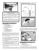
3) a. Move your engine forward or backward on the engine
mounts until you measure exactly 5-3/4" from the front face of the
prop drive washer to the front of the firewall. This is the distance
your engine needs to be from the firewall for proper cowl alignment
and prop clearance purposes.
Accurately mark the engine's
mounting bolt hole locations onto the engine mounts. Then set the
engine aside.
b. Drill the four engine mounting holes completely through
the mounts. Be very careful to drill them perpendicular to the
mount. Use a drill press if available.
c. Mount your engine in place on the engine mounts. We
suggest using a little thread locking compound (Loctite
®
) on the
mounting bolts to keep them from coming loose.
Note: This kit DOES NOT contain bolts for mounting your engine
to the engine mounts. That’s because not all .72-1.20 size engines
use the same size. Some engines may need 8-32 size bolts, while
others may need 10-32. You will need to go to the hobby shop to
obtain the correct size mounting bolts for your engine.
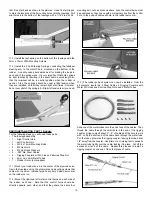
FUSELAGE ASSEMBLY, PART I: Engine Mounting:
For the following steps you will need these parts:
•
1 - Fuselage
•
2 - Glassed-Filled Engine Mounts *
•
4 - M4 x 25mm PWA Mounting Bolts
•
4 - M4 Blind Nuts
•
4 - M4 Flat Metal Washers
•
4 - M4 Split Lock Washers
•
Engine and suitable Mounting Bolts (not supplied)
* SAFETY: Size Limit on Glass-Filled Engine Mounts!
The glass-filled engine mounts provided in this kit are intended for
glow engines up to 1.20 cu.in., either 2-stroke or 4-stroke. Using
these mounts with larger engines is not recommended. Larger
engines should use an aluminum engine mount (not furnished).
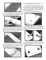
❑
1) Note that the horizontal and vertical thrust lines are scribed
into the front of the firewall. Also notice that the vertical thrust line
is slightly off center. This is to compensate for the 2
O
right thrust
that is already built into the fuselage.
a. Draw two parallel vertical lines exactly 1-1/16” on each
side of the vertical thrust line.
b. Draw two parallel horizontal lines exactly 1-13/64” on
each side of the horizontal thrust line.
(1-13/64” is just a thin
pencil line bigger than 1-3/16”)
c. The intersections of these four lines indicate where the
Blind Nuts need to be installed for the Engine Mounts. Use a 1/4"
dia. bit to drill four holes in the firewall for the M4 Blind Nuts.
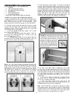
NOTE: The 2-1/8” total vertical spacing between the blind nuts,
along with the slotted holes in the engine mounts, should allow the
engine mounts to accomodate any engine that has a crankcase
width between 1-9/16” to 2-1/8”. That should cover most engines
that will be used in the Mayhem. If the width of your engine’s
crankcase is less than 1-9/16”, or more than 2-1/8”, you will have
to plan accordingly and adjust the dimension in step 1a above.
8
Building Tip: Inserting the blind nuts into the holes in the back
of the firewall, working through the belly of the fuselage, can be
a difficult job if you have big hands. A short stick and a little
piece of masking tape can make the job a lot easier. Simply
double back the tape and use it to hold
the blind nut on the end of the stick as
shown (a 1/4”sq. balsa stick is being use
in these pictures). This “handle” makes
it easy to insert and hold the blind nut in
the hole while you thread the mounting
bolt in from the front.