


❑
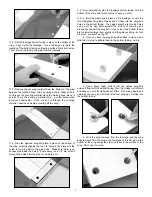
4) Each aileron pushrod consists of a Threaded Rod with a Hex
Nut, a R/C Link, and a Spring Keeper on each end.
Clip one end of the pushrod into the end hole of the servo arm.
Clip the other end of the pushrod into the middle hole of the
control horn. Adjust the overall length of the pushrod by screwing
the R/C links in or out as needed to get the aileron in neutral
position when the servo is in neutral position.
Because of the thickness of the MAYHEM airfoil, it is not easy to
determine exactly when the aileron is in neutral position. For this
reason we have supplied an Aileron Positioning Guide (APG). Cut
out the APG and use it to hold the aileron in true neutral position
when making your pushrod length adjustments.
❑
5) Once you have the pushrod length properly adjusted, slide
the spring keepers up onto the R/C links, and then screw the hex
nuts up tight against the end of the R/C links.
Put a drop of
Locktite
®
thread locking compound, or CA glue, on the hex nuts to
keep them from coming loose.
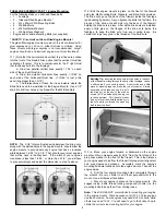
WING ASSEMBLY, PART V: Fitting the Wing to the Fuselage:
For the following steps you will need these parts:
•
The wing assembly
•
1 - Fuselage
•
1 - Plywood Wing Bolt Plate
•
2 - 1/4-20 x 2” Nylon Wing Bolts
•
2 - Fiberglass Wing Bolt Guides
•
1 - Fuselage Bottom Fairing
❑
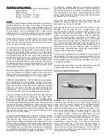
1) Trial fit the wing in place on the fuselage, using the two 1/4-
20 x 2” nylon bolts provided. The nylon wing bolts should pass
freely thru the holes near the trailing edge of the wing and thread
into the blind nuts that are pre-installed in the fuselage. Do not
overtighten the bolts - just snug them up enough to hold the wing
in place for the next step.
Note: If you have any difficulty mounting the wing to the fuselage,
find the cause of any binding now, and fix it before proceeding.
❑
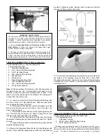
2) We need to draw guidelines on the ailerons to show where to
mount the control horns.
a. First draw a line paralell to the aileron hinge line, right at
the back edge of the aileron leading edge. Note: If you reflect light
off the aileron covering, you can clearly see the back edge of the
aileron leading edge. This piece is balsa wood. Right behind this
leading edge balsa is a piece of hardwood approximately 9/16”
wide. This hardwood piece is where the aileron control horn will be
mounted in the next step.
b. Use a straight edge to draw a second line on the aileron
which lines up with the last hole in the aileron servo arm. This line
should be 90
O
to the leading edge of the aileron.
❑
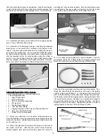
3) a. Locate the proper metal control horn for the aileron you
are working on (choose a control horn whose base will point the
same direction as the servo arm). Also locate four M2.6 x 10mm
Mounting Screws.
b. Set the control horn in place on the bottom of the aileron.
The front of the base of the control horn should be lined up with
line 2a, while the upright arm of the horn should be lined up with
line 2b.
Once you have the horn properly located, mark the
location of the four control horn mounting holes onto the aileron.
c. Drill a 3/64” dia. (or #56 drill) pilot hole into the aileron at
each mark. Do not drill completely through the aileron! Mount the
control horn in place using the M2.6 x 10mm Mounting Screws.
d. Repeat this process to mount a control horn on the other
aileron.
6
IMPORTANT: After you finish mounting the control horns on
the ailerons for the first time, take them back off and set them
aside temporarily. Then put a few drops of Thin CA into each
of the screw holes in the aileron. The Thin CA will soak into
the threads in the wood, and when it dries the holding power
of the threads will be much stronger. Use Thin CA only, not
medium or thick CA. Let the Thin CA dry completely before
remounting the control horns onto the ailerons.