background image

26

MIG Welding
1. 

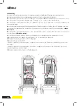
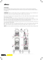
Insert the earth cable plug into the negative socket on the front of the machine and tighten it.

2. 

Plug the welding torch into the MIG torch connection socket on the front panel of the wire feeder, 

and tighten it.

IMPORTANT!  

When connecting the torch be sure to tighten the connection. A loose connection can 

result in the connector arcing and damaging the machine and gun connector.

3.

 Connect the water inlet and outlet pipe of MIG Gun to the water inlet and outlet


connectors on the 

front of the wire feeder.

4. 

Connect the gas line to gas connector on the rear panel of wire feeder. Check for Leaks!

5.

 Connect the control cable of wire feeder with the aero socket on the rear panel of welding machine.

6.

 Connect the cable of wire feeder with the positive output of welding machine.

7.

 Connect the water inlet and outlet pipe of wire feeder with the water inlet and outlet connectors on 

the rear front of cooling water.

8.

 Connect the control cable of cooling water with the aero socket on the rear panel of welding machine.

9.

 Connect the power cable of welding machine with the output switch in electric box on site.

DIAGRAM FOR GUN 


22 

Installation & Operation for MIG Welding 

Set up installation for MIG Welding 


(1) Insert the earth cable plug into the negative socket on the front of the machine and 

tighten it. 

(2) Plug the welding torch into the MIG torch connection socket on the front panel of the 

wire feeder, and tighten it. 

IMPORTANT:

 When connecting the torch be sure to tighten the connection. A loose 

connection can result in the connector arcing and damaging the machine and gun 
connector. 
(3) Connect the water inlet and outlet pipe of MIG Gun to the water inlet and outlet 

NOTE!

 Air cooling mode without cooling device and the water pipe is not needed for the air cooling mode.

Содержание Evolution MTS400 SYN

Страница 1: ...ration Manual www sifweld com Peters House The Orbital Centre Icknield Way Letchworth Garden City Hertfordshire SG6 1ET Tel 44 0 845 130 7757 MIG Approved TIG MMA TSXE3D400MTS SifWeld Evolution MTS400 SYN ...

Страница 2: ... EEA has been used in the design EN60974 1 Arc welding equipment Part 1 Welding power sources EN60974 10 Arc welding equipment Part 10 Electromagnetic Compatibility EMC requirements Additional information restrictive use Class A equipment intended for use in locations other than residential By signing this document the undersigned declares as manufacturer or the manufacturer s authorised represent...

Страница 3: ... as damp environments wearing wet clothing and metal structures Try to avoid welding in cramped or restricted positions Ensure that the equipment is well maintained Repair or replace damaged or defective parts immediately Carry out any regular main tenance in accordance with the manufacturer s instructions Safety against fumes and welding gases Locate the equipment in a well ventilated position Ke...

Страница 4: ...r the cutting welding area Remove all flammable and combustible materials from the cutting welding zone and surrounding areas Do not cut weld fuel and lubricant containers even if empty These must be carefully cleaned before they can be cut welded Always allow the cut welded material to cool before touching it or placing it in contact with combustible or flammable material Do not work in atmospheres...

Страница 5: ...ment that has reached its end of life must be collected separately and returned to an environmentally compatible recycling facility Handling of Compressed gas cylinders and regulators All cylinders and pressure regulators used in welding operations should be handled with care Never allow the electrode electrode holder or any other electrically hot parts to touch a cylinder Keep your head and face ...

Страница 6: ...TIG Display 13 2 3 MIG Manual Display 16 2 4 MIG SYN Display 17 2 5 Spool Gun Display 19 3 Installation 20 3 1 Torch switch Control 23 3 2 Remote Torch Control 24 3 3 Pedal Switch Control 25 3 4 Wire Feed Roller 29 3 5 Wire Installation 30 3 6 MIG Torch Liner 32 4 Operation 33 4 1 Spool Gun 33 5 Troubleshooting 36 6 Maintenance 37 7 Warranty 38 Contents ...

Страница 7: ...onsult an authorised SifWeld dealer or visit the SifWeld web site at www sifweld com The specifications presented in this manual are subject to change without prior notice Important notes Items in the manual that require particular attention in order to minimise damage and personal harm are indicated with the NOTE notation Read these sections carefully and follow their instructions Disclaimer Whil...

Страница 8: ...g IGBT technology and providing a lightweight multi process machine A separate wire feed system with full feature control Features 500A Three phase MIG welding machine with separate wire feed unit Synergic or manual settings Very high duty cycle 100 at 400A 60 at 500A Perfect machine for high production environment Supervisor lock out included Full digital control with large colour LCD Screen for ...

Страница 9: ...Evolution MTS400 SYN Input Voltage V Diameter mm 50 60 41 58 1 Fe 0 6 0 9 1 0 1 2 1 6 SS 0 8 0 9 1 0 1 2 1 6 Flux Cored 0 6 0 8 0 9 1 0 1 2 1 6 3 400 10 41 8 70 1 Al 1 0 1 2 1 6 0 75 MIG TIG 33 1 28 4 28 9 22 9 40 500 10 500 67 1 60 500A Protection class Circuit breaker Dimensions mm Weight Kg Power Factor IP21S D32A 620 x 260 x 430 33 8 10 500 MMA No load Voltage V ...

Страница 10: ... Connect the inlet of TIG gun 3 TIG gun control connector 4 Positive Output When TIG mode this polarity must conne 5 Gas Inlet Connect the gas conduit 6 Positive Output Used to connect to the welding cable of w 7 Wire feeder connector Used to connect to the control cab 8 Water Cooler connector To connect water box 9 Power source input To connect power source 10 Power switch Turn on power supply cl...

Страница 11: ...ater inlet for MIG red Wire feeder 1 MIG gun connector 2 9 core Gas Socket for Spool gun 3 Water outlet 4 Water inlet 5 Gas connector 6 Control anode 7 Positive output anode 8 Water inlet Water outlet 9 Wire reel Shaft 10 Wire Feed Motor 11 Wire feed tension adjustment 2x 12 Wire feed tension arm 2x 13 Wire feeder inlet guide 14 Wire drive roller 2x PANEL FUNCTIONS DESCRIPTIONS 6 Front and rear pa...

Страница 12: ...useful for electrode types that have a higher operating voltage requirement or joint types that require a short arc length such as out of position welds 1 Welding mode button Press it to select MMA welding mode 2 L parameter knob Rotate it to adjust welding current 3 R parameter knob Press it to select Hot start or Arc force and rotate it to adjust value Setting range 0 10 Hot start Hot start prov...

Страница 13: ... 4 Functional parameter button 5 Cooling mode button Press it to select water cooling mode TIG functional parameter interface 1 Trigger mode 2T or 4T 2 Down slope time 0 10s 3 Post flow time 0 10s 1 Welding mode button Press it to select TIG Lift welding mode 2 L parameter knob Rotate it to adjust welding current In functional parameter interface rotate it to select parameters 3 R parameter knob R...

Страница 14: ...e rotate it to select parameters 3 R parameter knob Rotate it to adjust Down Slope time and other parameters 4 Functional parameter button 5 Cooling mode button Press it to select water cooling mode TIG functional parameter interface 1 Trigger mode 2T or 4T 2 Down slope time 0 10s 3 Post flow time 0 10s 1 Trigger mode 2T or 4T 2 Down slope time 0 10s 3 Post flow time 0 10s ...

Страница 15: ...Gas Supply Wire Feed Output Voltage Output Current End Current conditions Self Locking Function 4T mode Latching Pre Gas Time Slow Feed Time Post Gas Time Welding conditions Gun Switch Gas Supply Wire Feed Output Voltage Output Current Burn back Time 2T mode ON OFF Trigger Mode Select ...

Страница 16: ...meter interface rotate it to select parameters 3 R parameter knob Rotate it to adjust parameters 4 Functional parameter button 5 Cooling mode button Press it to select water cooling mode 6 Manual shield gas check button 7 Manual wire feed button PANEL FUNCTIONS DESCRIPTIONS 1 panel 0 0 10S 12 t7 Electromagnetic valve is closed and stop argon flowing Welding is finished 3 2 4 MIG Manual display int...

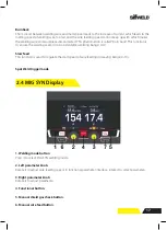
Страница 17: ...he optimal voltage and wire feed setting so the program provides a voltage fine tuning function for the synergic program selected Once the voltage is adjusted in a synergic program it will stay fixed at this variation when the current setting is changed To reset the voltage for a synergic program back to factory default change to another program and back again 1 Welding mode button Press it to sel...

Страница 18: ... Pulse 2 Wire material SS solid cored Fe solid cored Fe flux cored Al Mg solid cored CuSi 3 Wire diameter 0 6 1 6mm 4 Shield gas CO2 and Ar CO2 20 5 Pre flow time 0 10s The operator simply sets the welding current like MMA or TIG welding and the machine calculates the optimal voltage and wire speed for the material type wire type and size and shielding gas being used Obviously other variables such...

Страница 19: ... functional parameter interface rotate it to select parameters 3 R parameter knob Rotate it to adjust parameters 4 Functional parameter button 5 Manual shield gas check button 6 Manual wire feed button Spool Gun Functional Parameter interface PANEL FUNCTIONS DESCRIPTIONS 13 Spool Gun control panel 1 Welding mode button Press it to select Spool Gun welding mode 2 L parameter knob Rotate it to adjus...

Страница 20: ...able Details of the machine requirements can be found on the rating plate of the machine or in the technical parameters shown in the manual The equipment should be connected by a suitably qualified competent person Always ensure the equipment has a proper grounding Never connect the machine to the mains supply with the panels removed Output connections In general when using manual arc welding elect...

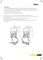
Страница 21: ...e electrode against the work piece to create and arc and hold the electrode steady to maintain the arc INSTALLATION OPERATION 1 4 Installation Operation 4 1 Installation Operation for MMA Electrode Welding 4 1 1 Set Up Installation Two sockets are available on this welding machine One Positive and one Negative polarity to connect MMA Electrode holder cable and earth clamp cable Various electrodes ...

Страница 22: ...ear panel Check for Leaks 9 Connect the power cable of welding machine with the output switch in electric box on site 10 Carefully open the valve of the gas cylinder set the required gas flow rate 11 Select TIG welding mode on the front panel 12 Set torch operation 2T 4T When 2T operation is selected press trigger Gas starts touch and lift arc start release trigger Gas and Arc stops When 4T operat...

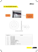
Страница 23: ...nected 5 Not connected 6 The button of UP input 7 The button of DOWN input 8 Trigger Switch Input 9 Trigger Switch Input 10 Not connected 11 The button of UP DOWN input 12 Not connected Remote Control Socket 3 1 Torch Switch Control Torch switch Adjust current button when it s pushed up the current increase when it s pushed down the current decrease ...

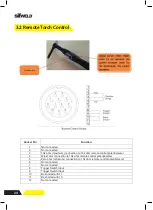
Страница 24: ... control potentiometer 4 Wiper arm connection to 10k ohm remote control potentiometer 5 Zero ohm minimum connection to 10k ohm remote control potentiometer 6 Not connected 7 Not connected 8 Trigger Switch Input 9 Trigger Switch Input 10 Be shorted with 11 11 Be shorted with 10 12 Not connected 3 2 Remote Torch Control Torch switch ...

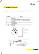
Страница 25: ...3 20k ohm maximum connection to 20k ohm remote control potentiometer 4 Wiper arm connection to 20k ohm remote control potentiometer 5 Zero ohm minimum connection to 20k ohm remote control potentiometer 6 Not connected 7 Not connected 8 Trigger Switch Input 9 Trigger Switch Input 10 Not connected 11 Not connected 12 Not connected When plug the twelve lead aero socket of pedal switch in it Welder wi...

Страница 26: ...eder with the positive output of welding machine 7 Connect the water inlet and outlet pipe of wire feeder with the water inlet and outlet connectors on the rear front of cooling water 8 Connect the control cable of cooling water with the aero socket on the rear panel of welding machine 9 Connect the power cable of welding machine with the output switch in electric box on site DIAGRAM FOR GUN Insta...

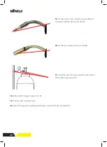
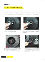
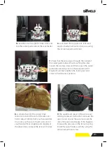
Страница 27: ...e through the inlet guide tube on to the drive roller 11 Feed wire over the drive roller into the outlet guide tube push the wire through approx 150mm 10 Place wire onto spool holder spool retaining nut is left hand thread Feed the wire through the inlet guide tube on to the drive roller 11 Feed wire over the drive roller into the outlet guide tube push the wire through approx 150mm 12 Close down ...

Страница 28: ...o be used for certain types of welding wire and they have different types of grooves machined in them to accommodate the different types of wire The wire is held in the groove by the top roller of the wire drive unit 13 Carefully open the gas cylinder valve and set the required gas flow rate 12 Fit the gas nozzle to the torch head 11 Fit the correct sized contact tip and feed the wire through it s...

Страница 29: ...lot less column strength can bend easily and is therefore more difficult to feed Soft wires can easily buckle at the wire feeder where the wire is fed into inlet guide tube of the torch The U shaped roller offers more surface area grip and traction to help feed the softer wire Softer wires also require less tension from the top pressure roller to avoid deforming the shape of the wire too much tens...

Страница 30: ...anate from poor set up of the wire into the wire feeder The guide below will assist in the correct setup of your wire feeder DIAGRAM FOR GUN 26 Wire Installation and Set Up Guide Again the importance of smooth consistent wire feeding during MIG welding cannot be emphasized enough The correct installation of the wire spool and the wire into the wire feed unit is critical to achieving an even and co...

Страница 31: ...f the spool and tangle If this happens increase the pressure on the tension spring inside the spool holder assembly using the INSTALLATION OPERAT 4 3 4 MIG Torch Liner Types and Informat MIG Torch Liners The liner is both one of the simplest and most impo sole purpose is to guide the welding wire from the wire up to the contact tip Steel Liners Most MIG gun liners are made from coiled steel wir 8 ...

Страница 32: ...eads to poor wire feeding and premature liner failure due to excessive wear By contrast larger diameter welding wires 1 2mm through 2 4mm have much higher columnar strength but it is important to make sure the liner has enough internal diameter clearance Most manufacturers will produce liners sized to match wire diameters and length of welding torch cable and most are color coded to suit Teflon an...

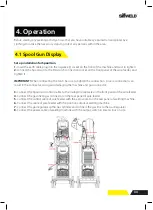
Страница 33: ...l of welding machine 6 Connect the cable of wire feeder with the positive output of welding machine 7 Connect the gas regulator to the Gas Cylinder and connect the gas line to the Gas Regulator 8 Connect the power cable of welding machine with the output switch in electric box on site DIAGRAM FOR GUN Set up installation for Spool Gun 1 Insert the earth cable plug into the Negative socket on the fr...

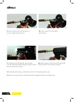
Страница 34: ...on electrical box 13 Carefully open the gas cylinder valve and set the required gas flow rate 14 Set welding parameters using the knobs as shown on digital displays 11 Feed the wire through the drive rolls and into the inlet guide tube Tighten the wire tension swing arm 12 Pull the trigger to drive the wire down the neck until it exits the contact tip 9 Remove the spool cover by pressing button an...

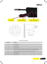
Страница 35: ...k ohm remote control potentiometer 7 Wiper arm connection to 10k ohm remote control potentiometer 8 Not connected 9 Not connected Remote Control Socket Gun switch Spool cover switch Adjust current button 4 5 6 7 8 9 Spool gun motor 10k ohm maximum connection to 10k ohm remote control potentiometer Zero ohm minimum connection to 10k ohm remote control potentiometer Wiper arm connection to 10k ohm r...

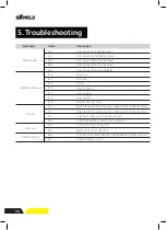
Страница 36: ...41 Over heating Program default Phase loss No water No gas Under voltage Over voltage Over current Wire feeder over load Button fault on operating panel when switch on the machine Other faults on operating panel when switch on the machine Torch fault when switch on the machine Torch fault during normal working process Cutting torch disconnection Water cooler disconnection Connection problem betwee...

Страница 37: ...or of the machine and the fan grills net of any dust and stains for example with a soft brush and vacuum cleaner Do not use pressurised air The stain may become compressed into the grooves of the coolers Do not use a pressure washing device 2 Check the electrical connections of the machine Clean any oxidised connections and tighten the loosened ones Check for the right tension before you start rep...

Страница 38: ...scope of the warranty Any warranty repair must be performed by Weldability Sif or an Authorised SifWeld Service Centre The customer is responsible for all shipping costs and risk associated with items that are returned covered under warranty Weldability Sif may opt to refund the purchase price less any costs and depreciation due to use and wear Faults defects found under warranty should be reporte...

Страница 39: ...39 Notes ...
Страница 40: ...40 www sifweld com Peters House The Orbital Centre Icknield Way Letchworth Garden City Hertfordshire SG6 1ET Tel 44 0 845 130 7757 Fax 44 0 800 970 7757 Email sales weldability sif com www sifweld com ...

Отзывы: