The E31 supports RISC‑V user mode, providing two levels of privilege: machine (M) and user
(U). U-mode provides a mechanism to isolate application processes from each other and from
trusted code running in M-mode.
See
The RISC‑V Instruction Set Manual, Volume II: Privileged Architecture, Version 1.10
for
more information on the privilege modes.
Physical Memory Protection (PMP)
The E31 includes a Physical Memory Protection (PMP) unit compliant with
The RISC‑V Instruc-
tion Set Manual, Volume II: Privileged Architecture, Version 1.10
. PMP can be used to set mem-
ory access privileges (read, write, execute) for specified memory regions. The E31 PMP sup-
ports 8 regions with a minimum region size of 4 bytes.
This section describes how PMP concepts in the RISC‑V architecture apply to the E31. The
definitive resource for information about the RISC‑V PMP is
The RISC‑V Instruction Set Manual,
Volume II: Privileged Architecture, Version 1.10
.
The E31 includes a PMP unit, which can be used to restrict access to memory and isolate
processes from each other.
The E31 PMP unit has 8 regions and a minimum granularity of 4 bytes. Overlapping regions are
permitted. The E31 PMP unit implements the architecturally defined
pmpcfgX
CSRs
pmpcfg0
and
pmpcfg1
supporting 8 regions.
pmpcfg2
and
pmpcfg3
are implemented but hardwired to
zero.
The PMP registers may only be programmed in M-mode. Ordinarily, the PMP unit enforces per-
missions on U-mode accesses. However, locked regions (see Section 3.7.2) additionally
enforce their permissions on M-mode.
The PMP allows for region locking whereby, once a region is locked, further writes to the config-
uration and address registers are ignored. Locked PMP entries may only be unlocked with a
system reset. A region may be locked by setting the
L
bit in the pmp
i
cfg register.
In addition to locking the PMP entry, the
L
bit indicates whether the R/W/X permissions are
enforced on M-Mode accesses. When the
L
bit is clear, the R/W/X permissions apply only to U-
mode.
Copyright © 2019, SiFive Inc. All rights reserved.
18
Содержание FE310-G002
Страница 1: ...SiFive FE310 G002 Manual v19p05 SiFive Inc ...
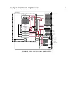
Страница 11: ...Figure 1 FE310 G002 top level block diagram Copyright 2019 SiFive Inc All rights reserved 9 ...
Страница 15: ...Chapter 2 List of Abbreviations and Terms 13 ...
Страница 23: ...Chapter 4 Memory Map The memory map of the FE310 G002 is shown in Table 4 21 ...


