


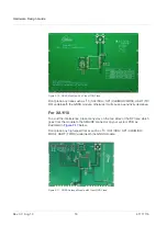


General Rules for Design
Rev 3.0 Aug.19
21
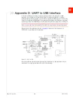
41111116
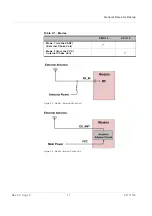
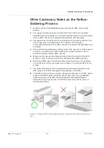
Figure 2-23: Examples of Independent Trace
Ground Segmentation
In general, the separation of ground between the GPS module and the rest of the
system is recommended to avoid interference. If this is not possible, it is best to
follow these rules: segmentation of ground between digital and analogue system,
high current and low current system, and different radiation systems such as GPS
and GPRS.
One way to segment the ground is to place digital and noise components at one
corner of the board, while placing analog and quiet components at the opposite
corner of the board. Make sure there is no crossing of microstrip or current
between the two component sets with ground; each set is to be contacted to one
point only.
Another method is to place the two different sets at different layers of the board,
while the ground of each layer is contacted at one point only which is ideally
located at the border of the board.
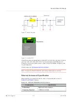
Ground Plane for XA1110
A large GND plane directly underneath the module can enhance the magnetic-
field line of the antenna for better GNSS signal reception. Typically it will improve
reception by up to ~2dB. It is strongly recommended that the ground plane
underneath the GNSS module be as large as possible.
The recommended thickness for the ground layer is 0.5 to 1 OZ (0.0175 to 0.035
mm). It is best to place the ground plane on the top layer of the PCB, directly
underneath the GNSS module as shown in
.