background image

10/12 

Building Technologies 

Electromotoric Actuators 

CA1N4505en 

HVAC Products 


26.10.2006 

4

5

0

5

A

0

2

(Y1)

(G)

(G0)

G

Y2

Y1

(Y2)

N2

Q1

Q2

Y2

(Y1)

(G)

(G0)

SP

SN

A

C

 2

4

 V

G

Y2

Y1

(Y2)

N1

Q1

Q2

Y1


N1, N2


Controller 

Y1, Y2


Actuator 

SP 

System potential AC 24 V 

SN 

System neutral 

Q1, Q2 

Controller contacts


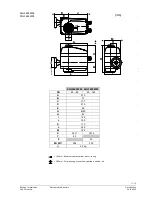
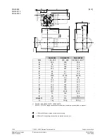
Dimensions 

Dimensions in mm 


*


Mounting height of actuator including ASK35... mounting kit = 168 mm 


> 100 mm: Minimum clearance from wall or ceiling 


> 200 mm: For mounting, connection, operation, service, etc. 


SQL85.00 

SQL35.00 
SQL85.00 

Содержание SQL35.00

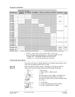
Страница 1: ...ltage AC 24 V 3 position control signal Nominal angle of rotation 90 Auxiliary switch and potentiometer for extra functions Manual adjuster and position indicator SQL36E built in heating element to avoid condensation SQL36E compatible with EN ISO 5211 flanges SQL36E variable positioning time with SEZ31 1 auxiliary module Use For operation of VKF41 VKF46 and VKF46 TS butterfly valves as control and...

Страница 2: ... 554 Z 05 Auxiliary switch and potentiometer 1000 Ω SQL35 00 SQL85 00 1 x ASC9 5 or 1 x ASC9 4 or 1 x ASZ7 4 only one accessory at a time can be mounted SEZ31 1 4505Z10 Auxiliary module for variable positioning time refer to Function mechanical design page 4 SQL36E65 SQL36E110 SQL36E160 ASC36 4505Z 19 Double auxiliary switch ASZ36 0 1000 Ω 4 50 5Z 28 Potentiometer 1000 Ω SQL36E50F04 SQL36E50F05 SQ...

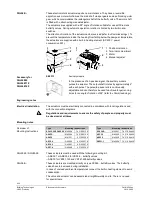
Страница 3: ...lves were replaced by VKF46 butterfly valves in 2000 For actuator retrofitting on installed butterfly valves replacement of actuators or ASK35 VKF45 40 125 Use SQL35 00 SQL85 00 actuators and ASK35 VKF45 150 200 Mounting of SQL36E65 actuator recommended Function mechanical design The actuator is driven by a 3 position signal from the controller and generates a rotary motion which is transferred vi...

Страница 4: ...adjustable and can therefore be used to achieve longer running times for an angle of rotation of 90 refer to Commissioning Engineering notes The actuators must be electrically connected in accordance with local regulations and with the connection diagrams Regulations and requirements to ensure the safety of people and property must be observed at all times Mounting notes Type Mounting Instructions...

Страница 5: ... its fully open position either manually or via positioning signal Y1 prior to activating the pump s The flow rate is adjusted either by driving the electric actuators as required or by operating the manual adjuster When using a SEZ31 1 auxiliary module set the desired positioning time SQL36E65 30 180 s SQL36E110 60 360 s SQL36E160 120 720 s 4505Z40 AUTO automatic operation 4290Z02 MAN manual oper...

Страница 6: ...aintenance Before performing any service work on the valve or actuator Switch off the pump and power supply Close the main shut off valves in the pipework Release pressure in the pipes and allow them to cool down completely If necessary disconnect electrical connections from terminals The valve must be re commissioned only with the manual adjuster or the actuator correctly assembled Disposal The a...

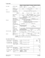
Страница 7: ...ick N474 Housing protection standard IP 44 to IEC 60529 IP 67 to IEC 60529 Protection class III or II to EN 60730 EN ISO 5211 32mm Flanges and shaft connection to actuator F04 F05 F07 F10 F12 F16 Dimensions weight Dimensions see Dimensions Cable glands 4 x 20 5 mm for M20 2 x M20 Weight 1 4 kg 4 5 kg 7 kg 14 kg 25 kg Materials Housing base yoke die cast aluminium Cover plastic die cast aluminium 1...

Страница 8: ...ms Cm1 End switch Cm2 End switch c1 1 auxiliary switch ASC9 5 or c1 c2 1 double auxiliary switch ASC9 4 or c1 1000 Ω 1 built in unit ASZ7 4 1 auxiliary switch and 1 potentiometer N Neutral conductor G System potential Y1 Control phase OPEN Y2 Control phase CLOSED 11 Sequence Y1 at 90 12 Sequence Y2 at 0 S1 End switch CLOSED S2 End switch OPEN S3 Auxiliary switch CLOSED ASC36 S4 Auxiliary switch OP...

Страница 9: ... switch CLOSED ASC36 S4 Auxiliary switch OPEN ASC36 S7 Thermal switch integrated H Heating element P1 Potentiometer ASZ36 T1 Auxiliary module SEZ31 1 Y1 Control phase OPEN Y2 Control phase CLOSED N Neutral conductor Connection diagrams 4505A01 L N N Y2 Y1 N2 Y1 Y2 Q1 Q2 Y2 L N L N AC 230 V N Y2 Y1 N1 Y1 Y2 Q1 Q2 Y1 N1 N2 Controller Y1 Y2 Actuator L System potential AC 230 V N System neutral Q1 Q2 ...

Страница 10: ...4 V G Y2 Y1 Y2 N1 Q1 Q2 Y1 N1 N2 Controller Y1 Y2 Actuator SP System potential AC 24 V SN System neutral Q1 Q2 Controller contacts Dimensions Dimensions in mm Mounting height of actuator including ASK35 mounting kit 168 mm 100 mm Minimum clearance from wall or ceiling 200 mm For mounting connection operation service etc SQL85 00 SQL35 00 SQL85 00 ...

Страница 11: ... M E A 4505M03 G Z Y B L I D H C K J M E A SQL36E50F04 SQL36E50F05 DN 40 65 80 125 A 210 B 73 C 137 D 210 E 65 G Ø 80 H 42 I 126 J 149 K 110 L 259 M 124 X 11 14 Y 42 Z 50 EN 5211 F04 F05 kg 4 5 kg 100 mm Minimum clearance from wall or ceiling 200 mm For mounting connection operation service etc SQL36E50F04 SQL36E50F05 ...

Страница 12: ...80 Ø 125 Ø 200 H 42 58 89 I 125 150 175 J 171 247 280 K 119 136 157 L 290 383 437 M 139 139 139 X 17 22 32 Y 70 102 165 Z 50 70 125 EN 5211 F07 F10 2 kg 7 kg 14 kg 25 kg 1 DN 350 400 VKF46 350TS VKF46 400TS 2 EN 5211 F12 F16 flange connections for third party actuators are available on request 100 mm Minimum clearance from wall or ceiling 200 mm For mounting connection operation service etc SQL36E...

Отзывы: