background image

SKP70…U.. Air/Gas Ratio Controlling Actuators

Technical Instructions

155-516P25

Rev. 2, December, 1998

Siemens Building Technologies, Inc

P

P

P

Pa

a

a

age 

ge 

ge 

ge 7

7

7

7    o

o

o

of 

f 9

9

9

9

Landis Division

St

St

St

Sta

a

a

arrrrt 

t up

up

up

up

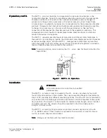
Regulator (

See

 Figures 2

and 3)

The pressure ratio and bias adjustment screws are located on top of the regulator under
a sealable cover plate. The actual settings can be seen through windows on each side of
the regulator.

N

N

N

No

o

o

otttte

e

e

e:::: The burner capacity is controlled by the position of the air damper. The

combustion quality (air/gas ratio) is controlled by the settings on the regulator (the
+ and – indications relate to the change in gas flow). Adjustment in clockwise
direction decreases the gas flow.

1.


Set the gas to air ratio to the desired value using the adjusting screw 

 (coarse

setting).

2.


Start the burner and run it at approximately 90% of full capacity.

3.


Measure CO

2

 or O

2

 content in the flue gases and correct the ratio by adjusting screw

 until optimum values are obtained (fine setting).

4.


Return to low fire and measure the CO

2

 or O

2

 content in the flue gases. If necessary,

correct the setting by adjusting screw 

 until optimum values are obtained.

5.


Limit the damper position for low fire operation. If considerable parallel displacement
was necessary to achieve optimum combustion, repeat the procedure from step 3.

6.


Run the burner to the required high fire position and limit the air damper position.

7.


Check the flue gas values at several intermediate output levels. If corrections are
necessary, note the following:

x


Adjust the pressure ratio screw 

 at high fire operation only.

x


Adjust the bias screw 

 at low fire operation only.

If the air pressure exceeds the maximum value of 12” or 20” w.c. (

See

Specifications), the pressure must be reduced by means of a pressure reducing
T-fitting (AGA78).

F

F

F

Fiiiig

g

g

gu

u

u

urrrre 

e 3

3

3

3. 

. A

A

A

Ad

d

d

djjjju

u

u

us

s

s

sttttm

m

m

me

e

e

en

n

n

ntttts

s

s

s....

Содержание SKP Series

Страница 1: ...he combustion air pressure without the need for an additional constant gas pressure regulator Since three functions safety shutoff constant pressure regulation and air gas ratio control can be performed by a single valve fewer components and fittings are required to assemble a gas train reducing both the size and the weight of the gas train significantly The total pressure drop across the gas trai...

Страница 2: ... fitting See Figure 4 AGA78 A motorized pressure reducing control SQN37 can also be installed in the air impulse line to continuously optimize combustion when used in conjunction with an oxygen trim system P P P Pr r r ro o o odu du du duc c c ct t t t N N N Nu u u um m m mb b b be e e er r r rs s s s T T T Ta a a ab b b bl l l le e e e 1 1 1 1 P P P Pr r r ro o o od d d du u u uc c c ct t t t N N...

Страница 3: ...imensions See Figure 6 Specification for valves See gas valve Technical Instruction No 155 512P25 Connections Conduit connection inch NPSM adapter Gas air combustion chamber pressure connections NPT Operating characteristics Output force 100 lb 450 N Maximum stroke 0 7 18 mm Opening time for maximum stroke 12 s Closing time 0 8 s Control signal Reference input signal Combustion air pressure Contro...

Страница 4: ... pressure acts on the regulator causing the air diaphragm to move to the left and close the regulating hydraulic bypass valve When the actuator is powered the gas valve begins to open The downstream differential gas pressure immediately begins to increase until the downstream gas pressure is in balance with the air pressure in accordance with the pressure ratio adjusted on the regulator The bypass...

Страница 5: ... SKP70 leakage due to diaphragm rupture stops when the burner shuts off and the valve is closed Conventional regulators continue to leak and therefore have to be vented to the outdoors N N N No o o ot t t te e e e To avoid oscillation do not oversize the VG valve See Technical Instruction No 155 512P25 F F F Fi i i ig g g gu u u ur r r re e e e 1 1 1 1 S S S SK K K KP P P P7 7 7 70 0 0 0 U U U U O...

Страница 6: ...c c ce e e e The pressure connection pipes should be as short as possible to allow the regulator to react to sudden changes The connection pipe for the combustion chamber pressure must be installed so that condensing flue gases cannot enter into the regulator but run back into the combustion chamber If necessary a water separator must be installed W W W WA A A AR R R RN N N NI I I IN N N NG G G G ...

Страница 7: ...oximately 90 of full capacity 3 Measure CO2 or O2 content in the flue gases and correct the ratio by adjusting screw until optimum values are obtained fine setting 4 Return to low fire and measure the CO2 or O2 content in the flue gases If necessary correct the setting by adjusting screw until optimum values are obtained 5 Limit the damper position for low fire operation If considerable parallel d...

Страница 8: ... Fi Fi Fitt tt tt tti i i in n n ng g g g A A A AG G G GA A A A78 78 78 78 F F F Fi i i ig g g gu u u ur r r re e e e 4 4 4 4 A A A AG G G GA A A A7 7 7 78 8 8 8 O O O Op p p pe e e er r r ra a a at t t ti i i io o o on n n n F F F Fi i i ig g g gu u u ur r r re e e e 5 5 5 5 A A A AG G G GA A A A7 7 7 78 8 8 8 A A A Ad d d dj j j ju u u us s s st t t tm m m me e e en n n nt t t ts s s s Function ...

Страница 9: ... d di ii ing ng ng ng T T T Te e e ec c c chn hn hn hno o o ol ll log og og ogi ii ie e e es s s s I I I In n n nc c c c Landis Division 1000 Deerfield Parkway Buffalo Grove IL 60089 4513 USA Document No 155 516P25 Printed in the U S A P P P Pa a a age ge ge ge 9 9 9 9 o o o of f f f 9 9 9 9 D D D Di i i im m m me e e en n n ns s s si i i io o o on n n ns s s s F F F Fi i i ig g g gu u u ur r r re...

Отзывы: