background image

Technical Instructions
Document No. 155-516P25
Rev. 2, December, 1998

P

P

P

Pa

a

a

age 

ge 

ge 

ge 4

4

4

4    o

o

o

of 

f 9

9

9

Siemens Building Technologies, Inc.

Landis Division

O

O

O

Op

p

p

pe

e

e

errrra

a

a

attttiiiio

o

o

on

n

n

n

((((S

S

S

See

ee

ee

ee    Fi

Fi

Fi

Fig

g

g

gur

ur

ur

ure 

e 1

1

1

1))))

Safety Shutoff Function

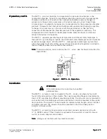
The electro-hydraulic actuator consists of a cylinder filled with oil and a piston
containing an electric oscillating pump and a hydraulic relief system. When power is
supplied to the actuator, the pump located at the base of the piston moves oil from the
reservoir (through an orifice) into the pressure chamber. The oil flow from the pump
through the orifice creates a pressure difference moving the diaphragm and the
attached spring loaded plug to the left, closing the return flow path from the pressure
chamber to the reservoir. This action causes the piston to move downward in the
cylinder opening the gas valve. When power to the pump is interrupted, the pressure
difference across the orifice instantly reduces to zero. The plug is immediately pushed
to the right allowing the oil to flow back from the pressure chamber into the reservoir,
closing the valve in less than 0.8 seconds. This unique hydraulic relief system provides
definite closure of the associated gas valve guaranteeing fail safe operation.

A visible disk fitted to the pump shaft indicates the entire stroke range of the actuator.
The disk also operates optional potential free switches via a set of levers. The
switching position of the auxiliary switch is adjustable over the entire stroke. The proof
of closure switch is non-adjustable.

Regulating Function

During the burner pre-purge period, when the gas valve is closed, only the air pressure
acts on the regulator causing the air diaphragm to move to the left and close the
regulating hydraulic bypass valve. When the actuator is powered the gas valve begins to
open. The downstream differential gas pressure immediately begins to increase until the
downstream gas pressure is in balance with the air pressure (in accordance with the
pressure ratio adjusted on the regulator). The bypass valve is now partially open so that
the oil flow supplied by the pump is identical to the return flow. Unlike conventional
direct acting regulators the SKP70… servo operated regulating system displays virtually
zero droop (offset) across the turndown range.

If, for example, heat demand increases, the air damper would open further increasing
the air pressure. The air diaphragm would move to the left, causing the bypass valve to
close and the gas valve to open further. The opening of the gas valve increases the
downstream gas pressure moving the gas diaphragm to the right until balance is
restored and the flow supplied by the pump is once again identical to the return flow
through the regulator bypass.

The gas to air pressure ratio is adjustable from 0.4:1 to 9:1. The setting is visible through
a window in the regulator. Once set, the gas to air pressure ratio remains constant over
the entire output range. The gas to air flow ratio will remain constant (provided that the
cross sections of the air and gas orifices in the burner head are fixed). The SKP70… is
not recommended for use with burners incorporating a sliding/continuously adjustable
head arrangement.

Many burner designs, because of reduced mixing energy at the low fire level, require
somewhat more low fire air in order to maintain optimum combustion parameters. To
accommodate this requirement the SKP70… incorporates a bias spring parallel
displacement adjustment which allows the characteristic of the regulator to be displaced
either towards excess air or reduced air.

Содержание SKP Series

Страница 1: ...he combustion air pressure without the need for an additional constant gas pressure regulator Since three functions safety shutoff constant pressure regulation and air gas ratio control can be performed by a single valve fewer components and fittings are required to assemble a gas train reducing both the size and the weight of the gas train significantly The total pressure drop across the gas trai...

Страница 2: ... fitting See Figure 4 AGA78 A motorized pressure reducing control SQN37 can also be installed in the air impulse line to continuously optimize combustion when used in conjunction with an oxygen trim system P P P Pr r r ro o o odu du du duc c c ct t t t N N N Nu u u um m m mb b b be e e er r r rs s s s T T T Ta a a ab b b bl l l le e e e 1 1 1 1 P P P Pr r r ro o o od d d du u u uc c c ct t t t N N...

Страница 3: ...imensions See Figure 6 Specification for valves See gas valve Technical Instruction No 155 512P25 Connections Conduit connection inch NPSM adapter Gas air combustion chamber pressure connections NPT Operating characteristics Output force 100 lb 450 N Maximum stroke 0 7 18 mm Opening time for maximum stroke 12 s Closing time 0 8 s Control signal Reference input signal Combustion air pressure Contro...

Страница 4: ... pressure acts on the regulator causing the air diaphragm to move to the left and close the regulating hydraulic bypass valve When the actuator is powered the gas valve begins to open The downstream differential gas pressure immediately begins to increase until the downstream gas pressure is in balance with the air pressure in accordance with the pressure ratio adjusted on the regulator The bypass...

Страница 5: ... SKP70 leakage due to diaphragm rupture stops when the burner shuts off and the valve is closed Conventional regulators continue to leak and therefore have to be vented to the outdoors N N N No o o ot t t te e e e To avoid oscillation do not oversize the VG valve See Technical Instruction No 155 512P25 F F F Fi i i ig g g gu u u ur r r re e e e 1 1 1 1 S S S SK K K KP P P P7 7 7 70 0 0 0 U U U U O...

Страница 6: ...c c ce e e e The pressure connection pipes should be as short as possible to allow the regulator to react to sudden changes The connection pipe for the combustion chamber pressure must be installed so that condensing flue gases cannot enter into the regulator but run back into the combustion chamber If necessary a water separator must be installed W W W WA A A AR R R RN N N NI I I IN N N NG G G G ...

Страница 7: ...oximately 90 of full capacity 3 Measure CO2 or O2 content in the flue gases and correct the ratio by adjusting screw until optimum values are obtained fine setting 4 Return to low fire and measure the CO2 or O2 content in the flue gases If necessary correct the setting by adjusting screw until optimum values are obtained 5 Limit the damper position for low fire operation If considerable parallel d...

Страница 8: ... Fi Fi Fitt tt tt tti i i in n n ng g g g A A A AG G G GA A A A78 78 78 78 F F F Fi i i ig g g gu u u ur r r re e e e 4 4 4 4 A A A AG G G GA A A A7 7 7 78 8 8 8 O O O Op p p pe e e er r r ra a a at t t ti i i io o o on n n n F F F Fi i i ig g g gu u u ur r r re e e e 5 5 5 5 A A A AG G G GA A A A7 7 7 78 8 8 8 A A A Ad d d dj j j ju u u us s s st t t tm m m me e e en n n nt t t ts s s s Function ...

Страница 9: ... d di ii ing ng ng ng T T T Te e e ec c c chn hn hn hno o o ol ll log og og ogi ii ie e e es s s s I I I In n n nc c c c Landis Division 1000 Deerfield Parkway Buffalo Grove IL 60089 4513 USA Document No 155 516P25 Printed in the U S A P P P Pa a a age ge ge ge 9 9 9 9 o o o of f f f 9 9 9 9 D D D Di i i im m m me e e en n n ns s s si i i io o o on n n ns s s s F F F Fi i i ig g g gu u u ur r r re...

Отзывы: