SKP70…U.. Air/Gas Ratio Controlling Actuators
Technical Instructions
155-516P25
Rev. 2, December, 1998
Siemens Building Technologies, Inc
P
P
P
Pa
a
a
age
ge
ge
ge 5
5
5
5 o
o
o
of
f
f
f 9
9
9
9
Landis Division
O
O
O
Op
p
p
pe
e
e
errrra
a
a
attttiiiio
o
o
on
n
n
n,
,
,
, c
c
c
co
o
o
on
n
n
ntttt’’’’d
d
d
d....
The SKP70… also has the ability to compensate for pressure disturbances in the
combustion chamber. Typically in installations where the resistance in the combustion
chamber and the stack is constant, the combustion chamber pressure changes in
proportion to the gas and air pressures as the burner output is varied. Under these
circumstances it is generally not necessary to compensate for the combustion chamber
pressure. If however, the combustion chamber pressure does not change in proportion
to the gas or air pressure (as is the case with flue gas dampers or flue gas fans),
connection of the combustion chamber pressure to the regulator is necessary. This
compensation circuit should also be employed when pressure shocks or vibrations
disrupts the burner startup phase.
The SKP70… regulator gas diaphragm incorporates an additional safety diaphragm. In
the event of a gas diaphragm rupture, the reinforced safety diaphragm serves to prevent
excessive leakage of gas. With the SKP70…, leakage due to diaphragm rupture stops
when the burner shuts off and the valve is closed. (Conventional regulators continue to
leak and therefore have to be vented to the outdoors.)
N
N
N
No
o
o
otttte
e
e
e:::: To avoid oscillation, do not oversize the VG… valve. (
See
Technical Instruction No.
155-512P25.)
F
F
F
Fiiiig
g
g
gu
u
u
urrrre
e
e
e 1
1
1
1.
.
.
. S
S
S
SK
K
K
KP
P
P
P7
7
7
70
0
0
0…
…
…
…U
U
U
U.....
.
.
. O
O
O
Op
p
p
pe
e
e
errrra
a
a
attttiiiio
o
o
on
n
n
n....
IIIIn
n
n
ns
s
s
stttta
a
a
all
ll
ll
lla
a
a
attttiiiio
o
o
on
n
n
n
W
W
W
WA
A
A
AR
R
R
RN
N
N
NIIIIN
N
N
NG
G
G
G::::
All installation must be carried out by qualified
personnel only.
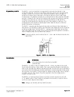
The SKP70… actuator is directly coupled to the VG… series valve body by four bolts
found in the terminal box of the actuator. The square mounting flange can be rotated in
steps of 90
o
providing four different mounting positions. The actuator can be mounted in
any position with the diaphragm vertically oriented but cannot be mounted in the upside
down position. The actuator can be mounted or replaced while the gas valve is installed
and under pressure. The actuator should be mounted so that the stroke position
indicator is clearly visible.
The SKP70… actuator packing contains an electrical conduit adapter to match with
½”-14 NPSM conduit. If the actuator is equipped with an auxiliary or proof of closure
switch, two such adapters are included.
N
N
N
No
o
o
otttte
e
e
e:::: Wiring must conform with local electrical codes.


