


3SK1 devices
5.1 3SK1 standard
3SK1 safety relays
52
Manual, 04/2013, A5E02526190021A/RS-AA/01
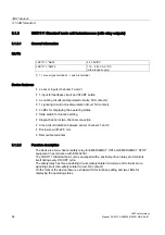
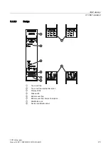
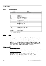
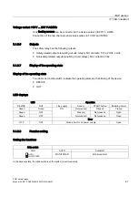
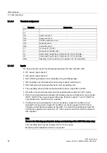
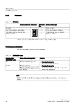
5.1.4.4
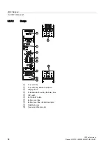
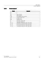
Terminal assignment
Terminal
Explanation
A1
+
A2
-
IN1
Sensor channel 1
IN2
Sensor channel 2
INS
START pushbutton circuit
INF
Feedback circuit
INK
Cascading circuit
T1
Test output 1 (for IN1)
T2
Test output 2 (for IN2, INF)
Q1
Safe output 1 (switching to P potential, 24 V DC solid-state)
Q2
Safe output 2 (switching to P potential, 24 V DC solid-state)
QM1
Signaling circuit 1 (switching to P potential, 24 V DC solid-state)
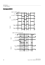
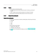
5.1.4.5
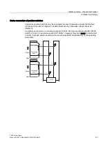
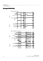
Inputs
The device has five inputs for safe signal processing: IN1, IN2, INS, INF, INK:
● IN1: sensor input channel 1
● IN2: sensor input channel 2
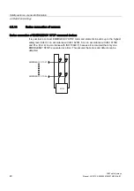
● INS: START pushbutton circuit (start after rising and falling edge)
● INF: Feedback circuit (checked for being closed: before switching on)
● INK: Cascading circuit (cascading input / normal switching duty
● The cascading circuit is AND-connected with the sensor inputs IN1 and IN2 .
● ON-button circuit and cascading circuit are activated with a 24 V DC signal.
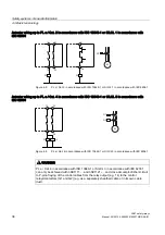
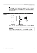
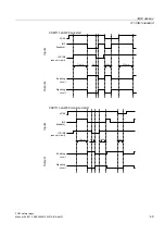
● With cross-circuit detection activated, the following inputs are checked for cross-circuits:
IN1/T1, IN2/T2. The supply is taken in this case from test outputs T1 and T2. INF/T2 is
only checked for a short-circuit to P potential.
● If "without cross-circuit detection" is set on the device, inputs IN1 and IN2 are not
checked for cross-circuits. Inputs IN1 and IN2 must not be supplied via T1/T2 here,
otherwise a fault will be generated via input INF. It is therefore essential that inputs IN1
and IN2 are supplied via an ex 24 V DC current source from which the device is
also supplied.
Note
Observe the following special points during commissioning of the 3SK1112 safety relay:
The cascading input must be jumpered if it is not to be used.
Monitoring of the feedback circuits is not optional.
Содержание SIRIUS 3SK1
Страница 2: ......
Страница 10: ...Table of contents 3SK1 safety relays 10 Manual 04 2013 A5E02526190021A RS AA 01 ...
Страница 14: ...Introduction 1 6 Correction sheet 3SK1 safety relays 14 Manual 04 2013 A5E02526190021A RS AA 01 ...
Страница 28: ...Product overview for 3SK1 3 5 3SK1 system 3SK1 safety relays 28 Manual 04 2013 A5E02526190021A RS AA 01 ...
Страница 94: ...3SK1 devices 5 4 3SK1 input expansions 3SK1 safety relays 94 Manual 04 2013 A5E02526190021A RS AA 01 ...
Страница 102: ...System configuration 6 3 System configuration rules 3SK1 safety relays 102 Manual 04 2013 A5E02526190021A RS AA 01 ...
Страница 186: ...Commissioning 3SK1 safety relays 186 Manual 04 2013 A5E02526190021A RS AA 01 ...
Страница 192: ...Display and diagnostics 12 4 Diagnostics 3SK1 safety relays 192 Manual 04 2013 A5E02526190021A RS AA 01 ...
Страница 242: ...Technical data 13 3 Expansion modules 3SK1 safety relays 242 Manual 04 2013 A5E02526190021A RS AA 01 ...
Страница 258: ...Accessories 3SK1 safety relays 258 Manual 04 2013 A5E02526190021A RS AA 01 ...
Страница 260: ...Appendix A 1 Correction sheet 3SK1 safety relays 260 Manual 04 2013 A5E02526190021A RS AA 01 ...
Страница 261: ......