Mounting and Commissioning
3.1 Mounting and Connections
SIPROTEC, 7SC805, Manual
C53000-G1140-C380-1, Release date 05.2014
81
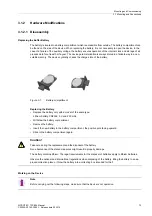
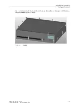
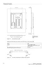
Housing Assembly
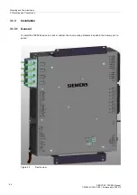
• Fix the device to the mounting brackets with 4 screws.
• Loosely screw the two mounting brackets into the rack or cabinet with 4 screws each.
• Tighten the 8 screws of the mounting brackets in the rack or cabinet.
• Connect a solid low-ohmic protective and operational ground to the grounding terminal of the device. The
cross-section of the cable used must correspond to the maximum connected cross-section but must be at
least 2.5 mm
2
.
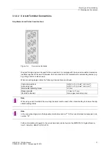
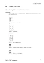
?tEstablish the connections according to the circuit diagram via the screwed connections. The details on the
connection technique for the communication modules in accordance with the SIPROTEC 4 System Descrip-
tion/1/ and the details on the connection technique for the current and voltage terminals on the rear of the
device in the Sections “Current Terminal Connections” and “Voltage Terminal Connections” must be strictly
observed.
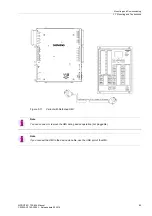
Note
When using current terminals, the mounting brackets must be used in the outmost setting to observe the stip-
ulated bending radius.
Содержание SIPROTEC 7SC805
Страница 8: ...Preface SIPROTEC 7SC805 Manual C53000 G1140 C380 1 Release date 05 2014 8 ...
Страница 18: ...Introduction 1 3 Characteristics SIPROTEC 7SC805 Manual C53000 G1140 C380 1 Release date 05 2014 18 ...
Страница 70: ...Functions 2 5 Device Operation SIPROTEC 7SC805 Manual C53000 G1140 C380 1 Release date 05 2014 70 ...
Страница 150: ...Literature SIPROTEC 7SC805 Manual C53000 G1140 C380 1 Release date 05 2014 150 ...


