background image

4.3.7

Transporting transportation units packed in boxes

Transportation with the fork-lift truck

WARNING

Danger when a transport unit/device tips over
If the forks are too short, this can cause the transportation unit/the device to tip over resulting 

in death, serious injury, or damage inside the cabinet. 
● The forks of the truck must protrude at the rear of the transportation unit. 
● Only use forklifts approved for the purpose of transporting the devices.

Transportation with the crane

WARNING

Danger due to falling transport unit/cabinet
If the lifting gear or load suspension devices were to fail, the transportation unit/the cabinet 

could fall. Death, serious injury, or material damage can result.
● Do not stand underneath or near to a raised load.

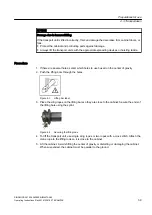
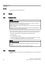
To protect the boxes against pressure, use sufficiently long rope and a spreader beam. Please 

proceed as follows:
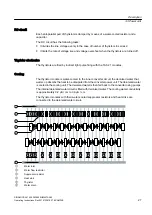
1. Attach the rope/cable to the pallet as shown in the following diagram.
2. Attach the rope/cable to the spreader beam 

 and the crane hook.

Preparations for use
4.3 Transportation

SINAMICS SL150 6SL38655UM427AA02

40

Operating Instructions Rev.201910281507  EXAMPLE

Содержание SINAMICS SL150 6SL38655UM427AA02

Страница 1: ...www siemens com drives Medium Voltage Drive SINAMICS SL150 Type 6SL38655UM427AA02 Operating Instructions Installation Instructions Edition 10 2019 This documentation pertains to EXAMPLE ...

Страница 2: ...28 10 2019 15 07 V18 00 ...

Страница 3: ...tructions This documentation pertains to EXAMPLE Edition 10 2019 Introduction 1 Safety information 2 Description 3 Preparations for use 4 Mounting 5 Electrical connection 6 Commissioning 7 Operation 8 Maintenance 9 Spare parts 10 Disposal 11 Service Support A Technical specifications and drawings B ...

Страница 4: ...ose who based on their training and experience are capable of identifying risks and avoiding potential hazards when working with these products systems Proper use of Siemens products Note the following WARNING Siemens products may only be used for the applications described in the catalog and in the relevant technical documentation If products and components from other manufacturers are used these...

Страница 5: ...witch 19 2 7 5 Measures for operator protection in electromagnetic fields 19 2 8 Residual risks 19 2 9 Security information 21 3 Description 23 3 1 Applications 23 3 2 Safety concept 23 3 3 Power unit 24 3 3 1 Product features 24 3 3 2 Power unit components 25 3 3 2 1 Components of the converter module 25 3 3 2 2 Design of the thyristor modules 26 3 3 2 3 AVT combination module 28 3 3 2 4 Power St...

Страница 6: ...t off the transport pallet 42 4 4 4 Opening doors in preparation for use 43 4 4 5 Checking the shock and tilt indicators inside the cabinet 43 4 5 Storage 44 4 5 1 Emptying the drive 44 4 5 2 Storing a device 44 5 Mounting 47 5 1 Safety instructions for installation 47 5 2 Torques 48 6 Electrical connection 51 6 1 Safety instructions for electrical connection 51 6 2 Note regarding unshielded cable...

Страница 7: ...stor 74 9 6 2 Replacing the snubber circuit capacitor 75 9 6 3 Replacing the CompactFlash card 76 9 6 4 Replacing the thyristor electronics and thyristors 76 9 6 4 1 Check components of the thyristor assembly 76 9 6 4 2 Replacing thyristor electronics 77 9 6 4 3 Replacing a thyristor 81 9 6 4 4 Disconnecting the fiber optic cables 83 9 6 5 Replacing components in the cooling circuit 84 10 Spare pa...

Страница 8: ...g circuit 31 Figure 4 1 Example of attaching and displaying the shock and tilt indicators 35 Figure 4 2 Example illustration of centers of gravity 37 Figure 4 3 Lifting bar label 39 Figure 4 4 Securing the lifting rods 39 Figure 4 5 Transporting a transportation unit still in packaging with a crane 41 Figure 4 6 Example Cover screw for manual door interlocking 43 Figure 6 1 Shield connection using...

Страница 9: ... of other persons and to avoid material damage carefully follow these instructions when carrying out any work If you have suggestions for improving the document please contact our Service Center Page 91 1 2 Text format features Text format features You can find the following text format features in these instructions 1 Handling instructions are always formatted as a numbered list Always perform th...

Страница 10: ...Introduction 1 2 Text format features SINAMICS SL150 6SL38655UM427AA02 10 Operating Instructions Rev 201910281507 EXAMPLE ...

Страница 11: ...n this documentation may only be operated by personnel qualified for the specific task in accordance with the relevant documentation for the specific task in particular its warning notices and safety instructions Because of their training and experience qualified personnel can recognize any risks involved with handling these products systems and avoid any possible dangers 2 3 The 5 safety rules Fo...

Страница 12: ...he connected machine is still turning high voltages can remain for a prolonged length of time High voltages can cause death or serious injury if the safety rules are not observed or if the equipment is handled incorrectly Operate the device properly Always follow the The five safety rules Page 11 when performing any work Service and maintain the device regularly and correctly Danger as a result of...

Страница 13: ...rty Observe the instructions regarding installation and operation Always take protective measures before touching any components Do not remove any covers Risk of burns due to hot component surfaces Certain components e g heat sinks and reactors can become very hot during operation These components can remain hot for a long time after operation Contact can result in serious injury such as skin burn...

Страница 14: ...gineering installations Electromagnetic fields are generated during operation of electrical power engineering installations Electromagnetic fields can interfere with electronic devices These devices can malfunction if electromagnetic fields are present WARNING Interference with pacemakers The functioning of cardiac pacemakers could be impaired by electromagnetic fields Death or serious physical in...

Страница 15: ...screen 10 cm Electronic components should not be brought into contact with electrically insulating materials such as plastic foil plastic parts insulating table supports or clothing made of synthetic fibers Bring components into contact only with ESD compliant materials e g ESD tables ESD surfaces ESD packaging Only carry out measurements on the components if one of the following conditions is met...

Страница 16: ... find the ambient and operating temperatures to be adhered to in the technical data If the described environmental conditions are not observed warranty claims and other claims may be rejected Explosions If you operate the device in a hazardous zone explosions can occur which can cause death serious injuries or material damage Never operate the device in an explosive atmosphere hazardous zone Non o...

Страница 17: ...arate cabinet units are connected properly cables and busbars All instructions for EMC compatible installation cabling shielding grounding and for adequate auxiliary power supply are to be observed Commissioning is only to be performed by qualified personnel trained for that purpose in accordance with the commissioning instructions System configuration is carried out by an experienced system integ...

Страница 18: ...tenance and access by unauthorized persons can lead to accidents The results can be death serious bodily injury or damage to property Install the device in electrical rooms where only qualified personnel have access If this is not possible then ensure that a barrier prevents uncontrolled access Use safety fences and appropriate signs for example to prevent unauthorized entry to the zone that has b...

Страница 19: ...omagnetic fields are subject to regulations BGV B11 and BGR B11 stipulated by the German statutory industrial accident insurance institution Display adequate hazard warning notices on the installation Place barriers around hazardous areas Take measures e g using shields to reduce electromagnetic fields at their source Make sure that personnel are wearing the appropriate protective gear 2 8 Residua...

Страница 20: ...re errors Operating and or environmental conditions outside of the specification External influences damage For instance a fault can have the following effects Extraordinarily high temperatures including open fires as a result of the fault Emissions of light noise particles or gases Devices with Open Type IP20 degree of protection must be installed in an electrical room or a comparable environment...

Страница 21: ...etworks In order to protect plants systems machines and networks against cyber threats it is necessary to implement and continuously maintain a holistic state of the art industrial security concept Siemens products and solutions only form one element of such a concept Customer is responsible to prevent unauthorized access to its plants systems machines and networks Systems machines and components ...

Страница 22: ...es relating to Industrial Security are provided here https support industry siemens com cs ww de view 109751848 en Safety information 2 9 Security information SINAMICS SL150 6SL38655UM427AA02 22 Operating Instructions Rev 201910281507 EXAMPLE ...

Страница 23: ...ponents Every converter is assigned a package with additional components The additional components comprise AVT combi voltage sensing current sensing and overvoltage limiting The additional components are required to assemble a complete device Note Auxiliary plant equipment All auxiliary equipment necessary for operation control and monitoring of the converter must be specified and incorporated by...

Страница 24: ...B6C 12 pulse output voltage One reversible converter bridge with number of thyristors in series R 2 1 B6C A B6C 6 pulse output voltage The thyristors are controlled optoelectronically via plastic fiber optic conductors The thyristors are fired via the thyristor electronics Structurally the two stacks are installed in parallel in a clamped assembly The open modules degree of protection IP00 stand o...

Страница 25: ... checkback signals via opto cables Two clamped thyristor stacks each with 12 thyristors 2 x 13 water cooled heat sinks each Suppressor capacitors Water cooled snubber resistors Figure 3 1 Schematic diagram Components of the converter module A module tower comprises three modules placed one on top of the other Description 3 3 Power unit SINAMICS SL150 6SL38655UM427AA02 Operating Instructions Rev 20...

Страница 26: ...9 9 9 9 9 9 9 9 9 9 9 9 Set of springs Thyristor Heat sink Clamping bolt Figure 3 2 Example Clamped thyristor assembly comprising 2 x 12 thyristors and 2 x 13 heat sinks The clamped thyristor assembly is pressed together by a set of springs with a clamping screw in such a way as to achieve the required contact force The purpose of the heat sinks is to dissipate heat losses Description 3 3 Power un...

Страница 27: ...verter circuit the deonized water that warms up absorbs the heat to be dissipated from the converter power unit The deionized water is cooled in the cooling unit The deionized water is then fed back to the converter using pumps The internal deionized water circuit is filled with deionized water The cooling water conductivity is approximately 0 2 µS cm to 0 6 µS cm The thyristor modules with their ...

Страница 28: ...Power Stack Adapter Figure 3 5 Example Power Stack Adapter The power stack adapter PSA acts as an interface between the power unit and the open loop closed loop controller The Power Stack Adapter is also where the power unit is electrically isolated from the open loop closed loop controller The DRIVE CLiQ serial communication interface ensures the exchange of data between the Power Stack Adapter a...

Страница 29: ... at no load These overvoltages can pose a danger to the converter For indoor systems surge arresters without spark gap are connected in a star configuration between the phases to limit the overvoltages 3 3 2 7 Overview of the additional components Table 3 1 Additional components for completion of the power module Order number Description Quantity installed in the converter not included in the scop...

Страница 30: ...istor control and monitoring system They work together with the Power Stack Adapter PSA The thyristor electronics can control all line side and motor side converters which are supplied with voltage by the gate current of the thyristor RC circuit The thyristor electronics module has the following tasks They generate the gate pulses for the thyristors Report information on the thyristor status the t...

Страница 31: ...hose measuring resistors are connected in series This ensures a high degree of measuring accuracy 36 ཱ 97 ི ུ 9 ཱི Measuring resistors AVT combination module Transformer for protective separation Voltage limitation 80 kHz power supply Figure 3 6 Overview of the voltage sensing circuit 3 4 Closed loop control 3 4 1 Description of the components 3 4 1 1 DC DC converter DC DC converters are used to pr...

Страница 32: ...Description 3 4 Closed loop control SINAMICS SL150 6SL38655UM427AA02 32 Operating Instructions Rev 201910281507 EXAMPLE ...

Страница 33: ... are being installed in general operating areas The operating areas must be dry and free of dust The air supplied must not contain any electrically conductive gas vapors or dust which could impair operation For information about permissible ambient and installation conditions see the Technical data and drawings section 4 1 2 Requirements placed on the levelness of the floor Ensure that the followi...

Страница 34: ...and tilt indicators Safe operation of the device is not guaranteed if the shock or tilt indicator has tripped responded This can result in death serious injury or material damage If one of the indicators has tripped do not perform any commissioning Inform the Technical Support Only specialist Siemens technicians can recommend appropriate measures See also Service Support Page 91 Preparations for u...

Страница 35: ... the load suspension devices attached to the equipment for possible damage Replace load suspension devices if they are damaged Before use check that the load suspension devices are correctly attached When lifting use only approved and undamaged lifting gear of sufficient rated capacity Check the lifting gear prior to its use WARNING Load suspension devices and lifting gear damaged If the load susp...

Страница 36: ...opriate licenses You must observe the specifications to avoid transport damage to the enclosure and you must maintain the permissible climatic conditions during operation in accordance with IEC 60721 3 1 2 3 Please also observe the Technical specifications instructions For lifting the device always use certified and adequately dimensioned cable guiding and spreading devices that are in absolutely ...

Страница 37: ...YLHZ 6LGH YLHZ Figure 4 2 Example illustration of centers of gravity 4 3 4 Transport with a fork lift truck WARNING Danger when a transport unit cabinet tips over If the forks are too short this can cause the transport unit cabinet to tip over resulting in death serious injury or damage to the cabinet The forks of the truck must protrude at the rear of the transport pallet The floor panels of the ...

Страница 38: ...apacity Pay attention to the center of gravity position If the cabinet center of gravity is off center use suitable lifting equipment e g a lifting beam If the cabinet has eye hooks use them In such cases do not use any lifting rods 4 3 6 Using lifting rods During transportation with a crane force is absorbed by the supporting frame of the cabinet The supporting frame remains on the unit The devic...

Страница 39: ...igure 4 3 Lifting bar label 3 Place the sling ropes on the lifting bars so they are close to the cabinet Secure the ends of the lifting bars using the splint Figure 4 4 Securing the lifting rods 4 To lift the transport unit use single sling ropes or two ropes with a cross stitch Attach the crane rope to the lifting rods so it is close to the cabinet 5 Lift the cabinet Avoid shifting the center of ...

Страница 40: ...sportation with the crane WARNING Danger due to falling transport unit cabinet If the lifting gear or load suspension devices were to fail the transportation unit the cabinet could fall Death serious injury or material damage can result Do not stand underneath or near to a raised load To protect the boxes against pressure use sufficiently long rope and a spreader beam Please proceed as follows 1 A...

Страница 41: ...TICE Incorrect storage of unpacked devices Proper packaging ensures that the equipment is protected Unpackaged equipment may be damaged if it is stored or out of service over a long period Carefully observe the instructions for storage in Chapters Storage and Technical data and drawings Remove the packaging immediately prior to installation The units are packed by the manufacturers in accordance w...

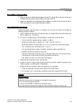
Страница 42: ...n bodily injury or death Release the retaining straps before opening Stay out of the way of the impact direction of the retaining straps NOTICE Improper removal of the load securing devices The load securing device protects the cabinet from any damage If you remove the load securing device improperly the cabinet may sustain damage Correctly remove the load securing device To extract the load secur...

Страница 43: ...oor interlocking 2 Insert a screwdriver into this opening 3 Turn the door handle until you feel resistance 4 Remove the screwdriver from the opening 5 Open the doors 4 4 5 Checking the shock and tilt indicators inside the cabinet Shock and tilt indicators are also located inside the cabinet Check these as soon as you have unpacked and opened the device To perform the check proceed as described in ...

Страница 44: ...gain empty the drive completely prior to storing To empty the drive proceed as follows 1 Open the connection between the cabinet piping and the external piping 2 Drain the coolant 3 Then tighten the screws again 4 At one of the flanges of the cabinet piping connect oil free compressed air or a nitrogen bottle Use a suitable transition element Blow out any residual water NOTICE Blow out pressure to...

Страница 45: ... below 20 C 4 F For lower temperatures agree on suitable measures together with Siemens Relative humidity should be less than 60 The floor of the place of storage must be sufficiently strong Do not exceed maximum permissible floor load levels or storage compartment load levels The ambient air must not contain any harmful gases Protect the device against shocks and humidity In order to ensure prote...

Страница 46: ... so that it is airtight Place a humidity meter that can be read from outside inside the film wrapping Observe the values provided in the technical specifications on relative humidity Check the values regularly using the humidity meter Inspect the device regularly Preparations for use 4 5 Storage SINAMICS SL150 6SL38655UM427AA02 46 Operating Instructions Rev 201910281507 EXAMPLE ...

Страница 47: ...ous injury and material damage Therefore remove dirt deposits after installation Then keep the doors closed In the event of contamination from conductive dust particles e g from welding work professional cleaning will be required Contact the service center in this regard Danger due to defective seals When working on the device seals at the doors roof panels as well as front rear and side panels ca...

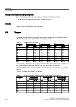
Страница 48: ... 221 M10 25 0 221 65 0 575 50 0 443 M12 50 0 443 115 0 1020 88 0 779 M16 115 0 1020 270 0 2390 215 0 1900 1 Examples of soft materials are Cu Al CuZn cable entries laminate materials plastics cast resin post insulators press nuts welding nuts blind rivet nuts and cage nuts 2 Hard materials S2 are materials with friction enhancing washer components e g a contact washer 3 Hard S1 materials include s...

Страница 49: ... 1 3 11 5 3 0 26 6 3 5 31 0 M8 1 8 15 9 3 9 34 5 7 2 63 7 M10 4 8 42 5 13 115 M12 18 159 3 M16 30 265 5 Observe the tightening torques of the terminal manufacturer and the test torques according to DIN EN 60999 1 VDE 609 1 Mounting 5 2 Torques SINAMICS SL150 6SL38655UM427AA02 Operating Instructions Rev 201910281507 EXAMPLE 49 ...

Страница 50: ...Mounting 5 2 Torques SINAMICS SL150 6SL38655UM427AA02 50 Operating Instructions Rev 201910281507 EXAMPLE ...

Страница 51: ...th serious injury and material damage To maintain the degree of protection after connecting the cable immediately seal the cable entries so they are air tight Danger caused by changing the floor panel or the roof panel If you make any changes to the floor panel or the roof panel in order to modify the cable entry the changes may mean that the requirements related to the specified degree of protect...

Страница 52: ... can cause damage Only use parts that consist of non magnetic material Material damage caused by high transition resistances Cables connected to the connection point that are not in compliance with the applicable regulations represent a high electrical transition resistance that can cause thermal damage contact erosion during operation Tighten the screws with the required torque Damage caused by i...

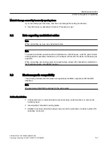
Страница 53: ...ng power and signal cables observe the instructions contained in the Electromagnetic compatibility section 6 3 Electromagnetic compatibility The following fundamental information and guidelines facilitate compliance with the EMC directives Note We recommend that EMC is planned for the entire plant Cabinet installation Connect painted or anodized metal components using contact washers or remove the...

Страница 54: ...es must cross at a right angle This especially involves sensitive and noisy signals Class 1 Unshielded cables for 60 V DC Unshielded cables for 25 V AC Shielded analog signal cables Shielded bus and data cables Operator panel interfaces incremental absolute encoder cables Class 2 Unshielded cables for 60 V DC and 230 V DC Unshielded cables for 25 V AC and 230 V AC Class 3 Unshielded cables for 230...

Страница 55: ...e shielding Incorrect connection or damaging of the cable shield can impair the function of the system Handle the cable shield carefully Ensure that the cable shield is correctly connected Bridge shield gaps at terminals circuit breakers contactors etc with minimum impedance and through the largest possible surface area Shield busbars Cables Terminals Figure 6 2 Bridging shield gaps Electrical con...

Страница 56: ... exiting via the cable filter auxiliary voltages in the control cabinet 6 4 Using the equipotential bonding strip and shield bus Each cabinet is equipped with an equipotential bonding or grounding bar to make it simpler to connect equipotential bonding conductors Connect all internal and external components to this equipotential bonding busbar is Attach the shields of incoming and outgoing cables ...

Страница 57: ...r connections have to be interconnected Detailed information about interconnecting these options with the interfaces is provided in the circuit manual 6 7 Fastening the cable ducts with cable ties Fasten all cable ducts whose cover faces downward with cable ties Wind the cable ties around the entire cable duct The cable ties must be located at the same positions as in the delivered state Figure 6 ...

Страница 58: ...Electrical connection 6 7 Fastening the cable ducts with cable ties SINAMICS SL150 6SL38655UM427AA02 58 Operating Instructions Rev 201910281507 EXAMPLE ...

Страница 59: ...ous injury or material damage Incorrectly performed commissioning can result in the warranty becoming null and void It is not permissible to commission the device if it is dirty Immediately contact Customer Support You can find the relevant contact person under Service Support This device may only be commissioned by electrically skilled persons who have been adequately trained on this product and ...

Страница 60: ...Commissioning SINAMICS SL150 6SL38655UM427AA02 60 Operating Instructions Rev 201910281507 EXAMPLE ...

Страница 61: ...may result in a fault signal In the event of continued operation serious aftereffects all the way to electric arcs are possible This can result in death serious injury or material damage Immediately switch off the device if a ground fault occurs during operation Then identify and eliminate the source of the ground fault The company operating the plant or system is responsible for the consequences ...

Страница 62: ...scription cause Remedy PWR Off 24 V power supply has failed or is too low 14 V or internal fuse defective Check input voltage If input voltage is 18 V and LED off Return component for repair Red Continuous light 24 V power supply is available 14 V internal board voltage fault Check input voltage If input voltage is 18 V and LED red Return component for repair Green Continuous light 24 V power supp...

Страница 63: ...ent in the com ponent LED is controlled irrespective of the cor responding messages being reconfig ured Remedy and acknowledge fault Green red 0 5 Hz flashing light Firmware download in progress 2 Hz flashing light Firmware download is complete Waiting for POWER ON Carry out a POWER ON Green orange or Red orange Flashing light Component recognition via LED is acti vated The color depends on the LE...

Страница 64: ...Operation 8 2 Fault and system messages SINAMICS SL150 6SL38655UM427AA02 64 Operating Instructions Rev 201910281507 EXAMPLE ...

Страница 65: ... a result of high voltages from external supplies Magnetizing and demagnetizing equipment that is fed from an external voltage source can result in high voltages This voltage can result in death or serious injury Ensure that no voltage from external feeds exists before commencing maintenance and repair work Danger due to high voltages of the snubber circuit capacitors The snubber circuit capacitor...

Страница 66: ... be removed at regular intervals or at least once a year by qualified personnel in line with the relevant safety regulations Note The actual intervals at which maintenance procedures are to be performed depend on the environmental and operating conditions Define maintenance intervals that reflect your plant specific environmental and operating conditions and meet your availability requirements Whe...

Страница 67: ...the equipment An inspection mainly comprises visual checks Inspections should be carried out based on a schedule that meets the needs of the special ambient conditions at the location of use The following servicing and inspection instructions are used as the basis for regular inspection of the equipment Maintenance work Carried out by Frequency Comments Check the cooling system Operating com pany ...

Страница 68: ...med depend on the environmental and operating conditions Define maintenance intervals that reflect your plant specific environmental and operating conditions and meet your availability requirements When doing so take the prescribed maintenance intervals into consideration as well as the instructions for repairing and replacing installed components 9 3 1 2 Checking the isolating clearances Slight d...

Страница 69: ... find a leak in a pipe coupling tighten the nut by a turn Compare the measured conductivity value with the permissible conductivity value for the system 0 6 µS cm You must replace the ion exchanger if this value is close to 1 µS cm Check the water level in the compensating chamber of the deionized water circuit If the level is too low add some more water If the level is too high drain some water u...

Страница 70: ...24 VDC power supply and communications line on the operator panel 4 Open the cover of the battery compartment 5 Remove the old battery 6 Insert a new battery 7 Close the cover of the battery compartment 8 Reconnect the 24 VDC power supply and communications line 9 Close the cabinet Note To ensure that no data is lost during a battery replacement it must be replaced within one minute If the time is...

Страница 71: ...e caused by aggressive cleaning agents Aggressive chemical agents can damage the electronics This can result in malfunction Never use any type of chemical agent or liquid Only remove severe dirt and contamination after prior consultation with service experts for the particular product Use a dry clean lint free ESD cleaning cloth Wipe all external parts of the rack with it Make sure that the dirt i...

Страница 72: ...es that have been treated with copper brass bronze or other heavy metals Use neither brass bronze or steel wire brushes nor cloths or steel wool interwoven with copper wire 9 5 2 Cleaning the cooling unit filter You can only clean the filter in front of the intake to the converter when the cooling unit has been switched off You can clean the filter at the output of the ion filter when the cooling ...

Страница 73: ...ial damage can occur if the device is recommissioned but the repair work carried out was not complete Check whether secondary faults have occurred on components which have failed Replace the components involved Measures in the event of an error It is not possible to fully test repairs that are carried out on site Return the defective module back to the manufacturing plant for repair The relevant a...

Страница 74: ...circuit is under pressure when you are working on it you can injure yourself The water circuit must always be in a no pressure state before commencing work on it Electrical connection Water connection Fastening nuts Figure 9 2 Replacing the snubber circuit resistor 1 Loosen the electrical connections on the resistor 2 Loosen the water hoses 3 Loosen the fastening nuts and remove the resistor 4 Ins...

Страница 75: ...r electronics are withdrawn Voltages of up to several 1000 V can occur and cause an electric shock This can result in death severe injuries and significant material damage In this case you should always handle the capacitors as if they were charged Discharge the snubber circuit capacitors Short circuit the snubber circuit capacitors before you withdraw the thyristor electronics Use heat stabilized...

Страница 76: ...the software key of the new CompactFlash card with the previous CompactFlash card the new CompactFlash card is not operational Consequently use the software key of the new CompactFlash card 4 Insert the new Siemens CompactFlash card 9 6 4 Replacing the thyristor electronics and thyristors 9 6 4 1 Check components of the thyristor assembly In the event of a thyristor assembly failing establish whic...

Страница 77: ...eath severe injuries and significant material damage In this case you should treat the capacitors as if they were charged Discharge the snubber circuit capacitors Short circuit the snubber circuit capacitors before you withdraw the thyristor electronics Figure 9 3 Thyristor rack position 9 6 4 2 Replacing thyristor electronics DANGER Danger when not complying with the five safety rules Non observa...

Страница 78: ... replaced proceed as follows Disconnecting the cables To disconnect the cables proceed as follows 1 If there are no core end markings label the two fiber optic cables and the connected cables 2 Remove all connecting leads 3 Detach the two fiber optic cables from the opto receiver and opto transmitter modules 4 Pull out the fiber optic cables Maintenance 9 6 Repairs SINAMICS SL150 6SL38655UM427AA02...

Страница 79: ... thyristor electronics The thyristor electronics are clamped very tightly in the connectors The thyristor electronics can be damaged during removal Never remove the thyristor electronics from the electronics shielding enclosure remove them from the heat sink only 3 Push the new thyristor electronics with component side facing to the right completely into the thyristor module slot There must be no ...

Страница 80: ... wood or plastic for shipping Use filler material to hold the thyristor electronics in place Enclose dehumidification material if the packaging is air tight Note the ESD in the Safety instructions section NOTICE Material damage due to inadequate packaging Components can be bent by careless packing or insufficient packaging This makes determining the exact cause of the error difficult When packing ...

Страница 81: ...ng with the five safety rules Work must only be performed on adequately grounded power unit Non observance of the five safety rules can cause death or serious injury Serious material damage can also result Observe the five safety rules You can replace thyristors within 5 minutes using simple tools Plastic holders support the thyristors against the heat sinks The heat sinks are suspended on springs...

Страница 82: ...y to the contact area 3 Place the new thyristor in the plastic holder Pay attention to the mounting position especially the polarity of the thyristor The adhesive symbols on the clamping pressure plates show the appropriate information 4 Reconnect the two twisted gating leads 5 Tighten the clamping screw with the socket wrench until the open ended wrench can be easily removed When the slot in the ...

Страница 83: ...the fiber optic cables carefully Do not bend them with a bending radius of less than 20 mm Protect the fiber optic cables from heat and strong light Knurled nut Fiber optic cable Figure 9 6 Releasing a fiber optic cable To disconnect the fiber optic cables proceed as follows 1 Carefully unscrew the knurled nut 2 Pull the fiber optic cable out 3 Insert the new fiber optic cable as far as it will go...

Страница 84: ...before commencing work on it Procedure To replace a component in the cooling circuit proceed as follows 1 Close the ball valves 2 Allow pressure to release 3 Open the union nut FEP hose Union nut Screwed joint O ring Connection e g cooler Figure 9 7 Replacing components in the cooling circuit 4 Replace the FEP hose or the O ring Maintenance 9 6 Repairs SINAMICS SL150 6SL38655UM427AA02 84 Operating...

Страница 85: ...ten the union nut with a torque of 1 2 Nm no gap between screwed joint and connection Note Recommissioning Operate the water circuit for at least two hours to remove the air bubbles from the system Maintenance 9 6 Repairs SINAMICS SL150 6SL38655UM427AA02 Operating Instructions Rev 201910281507 EXAMPLE 85 ...

Страница 86: ...Maintenance 9 6 Repairs SINAMICS SL150 6SL38655UM427AA02 86 Operating Instructions Rev 201910281507 EXAMPLE ...

Страница 87: ...er of the spare part required You can find the order number as follows The device label is attached to or next to each component Find out which item code the required spare part has The parts list provided specify the part number and where appropriate the article number corresponding to the equipment identifier For inquiries by e mail if possible send a photograph of the product spare part rating ...

Страница 88: ...Spare parts SINAMICS SL150 6SL38655UM427AA02 88 Operating Instructions Rev 201910281507 EXAMPLE ...

Страница 89: ...d old devices If you correctly dispose of the materials none of the materials pollutes the environment When disposing or reusing comply with the local laws and regulations WARNING Improper disassembly In the event of an improper procedure during disassembly material can slip tilt and fall down This can result in death serious injury or material damage Only specialist personnel may disassemble and ...

Страница 90: ... PCBs Electronic components Disposal 11 2 Removing device components and old devices SINAMICS SL150 6SL38655UM427AA02 90 Operating Instructions Rev 201910281507 EXAMPLE ...

Страница 91: ...e following data ready Type Serial number You can find this data on the rating plate Contact person If you wish to request on site service or order spare parts please contact your local office This office will contact the responsible service center on your behalf You can find your contact person in the relevant contact data base www siemens com yourcontact www siemens com yourcontact SINAMICS SL15...

Страница 92: ... executing a project Troubleshooting when faults develop Expanding a system or planning a new system Further you have access to the Technical Forum and other articles that our experts have drawn up FAQs Application examples Manuals Certificates Product announcements and many more The app is available for Apple iOS Android and Windows Phone Service Support A 2 SIOS App SINAMICS SL150 6SL38655UM427A...

Страница 93: ... only to the extent that it can be applied EU directives Machinery Directive 2006 42 EC amendments Electromagnetic compatibility 2014 30 EU amendments CE marking According to Low Voltage Direction only applies to the low voltage parts e g the control cabinet 2014 35 EU amendments Protection class Class 1 in accordance with DIN EN 61140 VDE 0140 Part 1 IEC 61140 Touch protection BGV A3 Insulation A...

Страница 94: ...ding to class 1K3 according to DIN EN 60721 3 1 IEC 60721 3 1 2K2 according to DIN EN 60721 3 2 IEC 60721 3 2 3K3 according to DIN EN 60721 3 3 IEC 60721 3 3 Pollution degree 2 without conducting contam ination according to DIN EN 61800 5 1 VDE 0160 T105 IEC 61800 5 1 2 without conducting contam ination according to DIN EN 61800 5 1 VDE 0160 T105 IEC 61800 5 1 2 without conducting contam ination a...

Страница 95: ...l flora Chemically active substan ces according to class 1C1 according to DIN EN 60721 3 1 IEC 60721 3 1 2C1 according to DIN EN 60721 3 2 IEC 60721 3 2 3C1 according to DIN EN 60721 3 3 IEC 60721 3 3 Mechanically active substan ces according to class 1S1 according to DIN EN 60721 3 1 IEC 60721 3 1 2S1 according to DIN EN 60721 3 2 IEC 60721 3 2 3S1 according to DIN EN 60721 3 3 IEC 60721 3 3 Tech...

Страница 96: ...Technical specifications and drawings B 2 Environmental conditions SINAMICS SL150 6SL38655UM427AA02 96 Operating Instructions Rev 201910281507 EXAMPLE ...

Страница 97: ...idge 31 Current conduction permanent signals 31 Current transformer 29 D Door interlock Cover screw 43 Manual 43 DRIVE CLiQ 28 E Electromagnetic fields 14 Environmental conditions 94 F Fiber optic cables 30 83 Fuse Power Stack Adapter 62 G Gate pulses 30 Grounding ESD shoe grounding strips 15 Grounding concept 18 Grounding harness 67 Grounding point 54 High voltage after shutdown 67 Protective gro...

Страница 98: ...rpose 34 Siemens Industry Online Support App 92 Snubber circuit capacitor 75 Spare parts 91 Contact person 87 Spares On Web 87 Storage Drive unit 44 General specifications 45 Preconditions 45 Storage duration 45 Surge arresters 29 T TAS CPLD 30 Technical Support 91 Thyristor 30 Thyristor assembly 76 Thyristor electronics 30 78 Thyristor electronics power supply 30 Thyristor state 30 Time coded fee...

Страница 99: ......

Страница 100: ...0009993865 000010 01 EN 01 000999386500001001EN01 000999386500001001EN01 Further Information www siemens com LDA Siemens AG Large Drives Applications Vogelweiherstr 1 15 90441 NÜRNBERG GERMANY ...

Страница 101: ...NMA LDA EN Tel 49 911 433 6422 Fax 49 911 433 6921 Email motoren doku aud internal siemens co m Our ref 0009993865000010 Date 28 10 2019 Documentation for 6SL38655UM427AA02 Your order no 000010 AL N ECCN N UL DE StWanr CD 85234045 StWanr Print 49011000 Dear Sir Madam Many thanks for your order the documentation for which is enclosed Yours very truly 000999386500001001EN01 ...

Страница 102: ......

Страница 103: ...r binder 50 mm 120 g m2 SINAMICS SL150 6SL38655UM427AA02 EXAMPLE Operating Instructions Spine label for binder 145 mm 120 g m2 SINAMICS SL150 6SL38655UM427AA02 EXAMPLE Operating Instructions Installation Instructions ...

Страница 104: ......

Отзывы: