SIMPRO-100
Settings Calculation
4
PRIM-2400C
67
4.7.3
Front-Panel Display
Message Settings
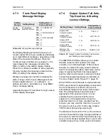
Table 4.36
Display Message Settings
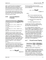
The Display Messages function allows you to
monitor a total of four logic conditions and display
up to eight different messages, depending on the
state of the monitored conditions. When the
monitored logic condition is true (logical 1), the
relay displays the message entered as the
DMn_1 setting in the default display rotation.
When the monitored condition is false (logical 0),
the relay displays the message entered as the
DMn_0 setting in the display rotation.
Display messages are useful for indicating the
state of relay contact inputs. Message text can
include capital letters A – Z, numbers 0 – 9,
spaces, periods (.), and dashes (-). Type
NA
to
clear a message setting.
Appendix B, page 137 describes the logic used to
control display messages.
4.7.4
Output Contact Fail-Safe,
Trip Duration, & Starting
Lockout Settings
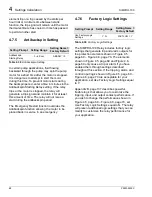
Table 4.37
Output Contact Fail-Safe, Trip Duration,
and Starting Lockout Settings
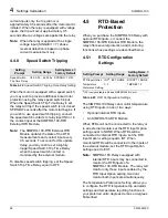
The SIMPRO-100 Relay allows you to enable
fail-safe output contact operation for relay
contacts on an individual basis. When contact
fail-safe is enabled, the relay output contact is
held in its energized position when relay control
power is applied and falls to its deenergized
position when control power is removed. Output
contact deenergized positions are indicated on
the relay chassis and in Figure 2.11, page 33.
When TRIP Contact Fail-safe is enabled and the
TRIP output contact is appropriately connected to
the motor breaker or contactor, the motor is
automatically tripped when relay control power
fails. This setting/connection philosophy is
appropriate if the protected motor is more
valuable than the process that the motor
supports. In critical applications where the
protected motor is not more valuable than the
process, you may want the motor to run even if
the relay is out of service. In this case, disable
TRIP Contact Fail-safe by selecting N.
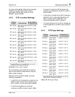
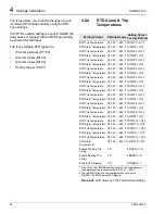
The Minimum Trip Duration Time is the minimum
amount of time that the relay trip signal will last in
the event of a fault. Set this time at least as long
as your motor breaker operate time or your motor
contactor dropout time. In the event of a thermal
Setting
Prompt
Setting Range
Setting Name =
Factory Default
Display
Messages
20 characters;
enter NA to NULL
DM1_1 = SIMPRO-100
DM1_0 =
DM2_1 = MOTOR RELAY
DM2_0 =
DM3_1 = RTD FAILURE
DM3_0 =
DM4_1 =
DM4_0 =
Setting Prompt Setting Range
Setting Name =
Factory Default
Enable TRIP
Contact Fail-safe
Y, N
TRFS = Y
Enable OUT1
Contact Fail-safe
Y, N
OUT1FS = N
Enable OUT2
Contact Fail-safe
Y, N
OUT2FS = N
Enable OUT3
Contact Fail-safe
Y, N
OUT3FS = N
Minimum Trip
Duration Time
0.00 – 400.00 s
TDURD = 0.50
Содержание SIMPRO-100
Страница 1: ...SIMPRO 100 Motor Protection Relay Instruction Manual Document No PRIM 2400C ...
Страница 12: ...Contents SIMPRO 100 x PRIM 2400C ...
Страница 16: ...Contents SIMPRO 100 xiv PRIM 2400C ...
Страница 42: ...3 SIMPRO PC Software SIMPRO 100 40 PRIM 2400C ...
Страница 50: ...4 Settings Calculation SIMPRO 100 48 PRIM 2400C Figure 4 2 Generic Thermal Limit Curves Cold Motor ...
Страница 100: ...6 ASCII Serial Port Operation SIMPRO 100 98 PRIM 2400C ...
Страница 127: ...SIMPRO 100 Event Analysis 9 PRIM 2400C 125 Figure 9 2 Example SER Report ...
Страница 136: ...10 Maintenance Troubleshooting SIMPRO 100 134 PRIM 2400C ...
Страница 138: ...A Firmware Versions SIMPRO 100 136 PRIM 2400C ...
Страница 147: ...SIMPRO 100 Control Equations Relay Logic B PRIM 2400C 145 Figure B 3 Display Message Variables ...
Страница 157: ...SIMPRO 100 Control Equations Relay Logic B PRIM 2400C 155 Figure B 16 Overvoltage Element Logic ...
Страница 206: ...D SIMPRO PC Compatibility Features SIMPRO 100 204 PRIM 2400C ...
Страница 214: ...E Motor Thermal Element SIMPRO 100 212 PRIM 2400C ...
Страница 230: ...F SIMPRO 100 Relay Settings Sheets SIMPRO 100 228 PRIM 2400C ...
Страница 239: ......

