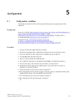
Siemens SIMOTICS M-1FE2 Скачать руководство пользователя страница 76

Configuration 


5.1 Configuration workflow 


SIMOTICS M-1FE2 built-in motors 

74


Configuration Manual, 05/2021, A5E50494252B AB 

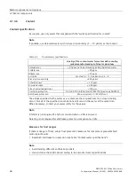
1. Clarification of type of drive 

The motor is selected based on the required torque, which is defined by the application.  
The 1FE2 is used for main spindle drives. 
As well as the load torque, which is determined by the application, the following mechanical 

data is required to calculate the torque to be provided by the motor: 


Masses to be moved 


Frictional resistance data 


Mechanical efficiency 


Max. speed 


Maximum acceleration and maximum deceleration 


Cycle time 

The following points must also be taken into account: 


The line system configuration, when using specific types of motor and/or line filters on IT 

systems (non-grounded systems). 


The ambient temperatures and the installation altitude of the motors and drive 

components. 

The motor-specific limiting characteristics provide the basis for defining the motors. The 

limiting characteristics describe the torque or power curve via the speed. The limiting 

characteristics show the limits of the motor on the basis of the DC-link voltage of the Power 

Module or Motor Module.  
The DC-link voltage is turn dependent on the supply voltage and on the type of Line Module. 

2. Definition of constraints and integration into the automation system 

When configuring, take account of the utilization of the motor according to rated values for 

the winding overtemperature of 100 K. 
Other marginal conditions are imposed by the integration of the drives into the automation 

environment. 
The appropriate automation system, such as SINUMERIK, is used for motion control functions 

and for synchronous functions. 
The drives are interfaced to the higher-level automation system via PROFIBUS. 

3. Definition of load cycle, calculation of max. load torque, definition of motor 

The motor-specific limiting characteristics provide the basis for defining the motors. 
The limiting characteristics define the torque characteristic with respect to speed and take 

into account the motor limits based on the line supply voltage and the function of the infeed. 

Содержание SIMOTICS M-1FE2

Страница 1: ......

Страница 2: ......

Страница 3: ...al 05 2021 A5E50494252B AB Introduction Fundamental safety instructions 1 Description 2 Mechanical properties 3 Motor components and options 4 Configuration 5 Preparing for use 6 Installation 7 Connecting 8 Technical data and characteristics 9 Dimension drawings 10 Environmental compatibility 11 Appendix A A ...

Страница 4: ... only by personnel qualified for the specific task in accordance with the relevant documentation in particular its warning notices and safety instructions Qualified personnel are those who based on their training and experience are capable of identifying risks and avoiding potential hazards when working with these products systems Proper use of Siemens products Note the following WARNING Siemens p...

Страница 5: ...s and Configuration Manuals More information Information on the following topics is available at Additional links to download documents Using documentation online find and search in manuals information More information https support industry siemens com cs de en view 108998034 If you have any questions regarding the technical documentation e g suggestions corrections please send an e mail to the f...

Страница 6: ...ncontrol Internet address for SINAMICS http www siemens com sinamics Target group This documentation addresses project planners and project engineers as well as machine manufacturers and commissioning engineers Benefits The Configuration Manual enables the target group to apply the rules and guidelines to be observed when configuring products and systems The Configuration Manual supports you with ...

Страница 7: ...ons of clarity this documentation does not contain all of the detailed information on all of the product types This documentation cannot take into consideration every conceivable type of installation operation and service maintenance Information regarding third party products Note Recommendation relating to third party products This document contains recommendations relating to third party product...

Страница 8: ...Introduction SIMOTICS M 1FE2 built in motors 6 Configuration Manual 05 2021 A5E50494252B AB ...

Страница 9: ...meplate data 36 2 6 1 Rating plate details type plate of 1FE2 in synchronous version 36 2 6 2 Rating plate details type plate of 1FE2 in asynchronous version star connection 37 2 6 3 Rating plate details type plate of 1FE2 in asynchronous version star delta connection 38 2 7 Selection and ordering data 39 2 8 Structure of the Article No 40 3 Mechanical properties 43 3 1 Types of construction 43 3 ...

Страница 10: ...llation overview for asynchronous rotors brief description 99 7 2 3 Balancing the asynchronous version 100 7 2 4 Installation overview for synchronous rotors brief description 101 7 2 5 Balancing the synchronous version 101 7 2 6 Removing the rotor brief description 104 7 3 Installing the stator 105 7 3 1 Production equipment assembly tools and other resources 105 7 3 2 Installing the stator brief...

Страница 11: ... 8 2 3 3 Conversion of the converter setting data 138 9 Technical data and characteristics 143 9 1 Explanations 143 9 2 Technical data 144 9 2 1 Technical data for the synchronous version 144 9 2 2 Technical data for the asynchronous version 145 9 3 Characteristics 146 10 Dimension drawings 147 11 Environmental compatibility 149 A Appendix A 151 A 1 Technical data and dimensions of the recommended...

Страница 12: ...Table of contents SIMOTICS M 1FE2 built in motors 10 Configuration Manual 05 2021 A5E50494252B AB ...

Страница 13: ...no voltage between any of the power connections and between any of the power connections and the protective conductor connection 5 Check whether the existing auxiliary supply circuits are de energized 6 Ensure that the motors cannot move 7 Identify all other dangerous energy sources e g compressed air hydraulic systems or water Switch the energy sources to a safe state 8 Check that the correct dri...

Страница 14: ... WARNING Electric shock if there is no ground connection For missing or incorrectly implemented protective conductor connection for devices with protection class I high voltages can be present at open exposed parts which when touched can result in death or severe injury Ground the device in compliance with the applicable regulations WARNING Arcing when a plug connection is opened during operation ...

Страница 15: ...es or mobile telephones in the immediate vicinity of the components can result in equipment malfunction Malfunctions may impair the functional safety of machines and can therefore put people in danger or lead to property damage Therefore if you move closer than 20 cm to the components be sure to switch off radio devices or mobile telephones Use the SIEMENS Industry Online Support app only on equip...

Страница 16: ... Safety Integrated functions you must observe the safety notices in the Safety Integrated manuals WARNING Active implant malfunctions due to electromagnetic fields Electromagnetic fields EMF are generated by the operation of electrical power equipment such as transformers converters or motors People with pacemakers or implants are at particular risk in the immediate vicinity of this equipment If t...

Страница 17: ... of motors Comply with the specified cooling requirements for the motor WARNING Fire due to incorrect operation of the motor When incorrectly operated and in the case of a fault the motor can overheat resulting in fire and smoke This can result in severe injury or death Further excessively high temperatures destroy motor components and result in increased failures as well as shorter service lives ...

Страница 18: ...c discharge Electric fields or electrostatic discharge can cause malfunctions through damaged individual components integrated circuits modules or devices Only pack store transport and send electronic components modules or devices in their original packaging or in other suitable materials e g conductive foam rubber of aluminum foil Only touch components modules and devices when you are grounded by...

Страница 19: ...elopment to make them more secure Siemens strongly recommends that product updates are applied as soon as they are available and that the latest product versions are used Use of product versions that are no longer supported and failure to apply the latest updates may increase customer s exposure to cyber threats To stay informed about product updates subscribe to the Siemens Industrial Security RS...

Страница 20: ...mage X ray ionizing radiation and cosmic radiation 2 Unusually high temperatures including open flames as well as emissions of light noise particles gases etc can occur inside and outside the components under fault conditions caused by for example Component failure Software errors Operation and or environmental conditions outside the specification External influences damage 3 Hazardous shock volta...

Страница 21: ... affected person maintain a minimum separation of 500 mm to motors If you wish to use special versions and design variants whose specifications vary from the motors described in this document then contact your local Siemens office If you have any questions regarding the intended usage please contact your local Siemens office Built in motors are components for installation in machines and for deplo...

Страница 22: ...he spindle manufacturer results in a motor spindle unit WARNING Danger to life through the use of an incomplete machine If you use a machine that does not conform to the 2006 42 EU decree there is the danger of death severe injury and or material damage Commission the machine only when it conforms to the regulations of the EU 2006 42 EU machine decree and the conformity has been declared 2 2 Overv...

Страница 23: ...t 3 Installed 1FE2 built in motor shown without shaft 1 Rotor with short circuit cage 2 Stator without cooling jacket Standard 3 Installed 1FE2 built in motor shown with out shaft Design with cooling jack et 1 Rotor with externally mounted permanent magnets APM 2 Stator with cooling jacket optional 3 Installed 1FE2 built in motor shown without shaft Frame sizes shaft heights 16 pole 1FE218 8L A co...

Страница 24: ...system Encoder system 1 Encoder 6 Drain hole 2 Stator with cooling jacket 7 Inlet cooling water connection 3 Rotor with sleeve 8 Spindle housing 4 Spindle shaft with bearings 9 Outlet cooling water connection 5 End shield DE Drive End 10 End shield NDE Non Drive End Figure 2 1 Motor spindle design Note The spindle manufacturer is responsible for designing the bearings lubrication and cooling A fer...

Страница 25: ...34 7 Connection designations EN 60034 8 Noise levels 1 EN 60034 9 Temperature monitoring EN 60034 11 Vibration severity grades 1 EN 60034 14 1 Standard component e g cannot be applied to built in motors Relevant directives The following directives are relevant for SIMOTICS motors European Low Voltage Directive SIMOTICS motors comply with the Low Voltage Directive 2014 35 EU European Machinery Dire...

Страница 26: ...ation of this directive Eurasian conformity SIMOTICS motors comply with the requirements of the Russia Belarus Kazakhstan EAC customs union China Compulsory Certification SIMOTICS motors do not fall within the scope covered by the China Compulsory Certification CCC CCC negative certification CCC product certification https support industry siemens com cs products search CCC dtp Certificate mfn ps ...

Страница 27: ...tection 1 x PTC thermistor triplet 3 sensors in series Can be evaluated e g using a thermal motor protection unit Order No 3RN2013 1GW130 Universal protection optional Full protection NTC PT3 51 F NTC K227 Winding insulation Temperature class 155 F acc to EN 60034 At a coolant temperature of 20 C an average winding overtemperature of 125 K is permitted The performance data applies for a cooling wa...

Страница 28: ...N CC1 1 05 80 95 150 1FE2184 8LK CC1 1 05 80 95 150 1FE2184 8LH CC1 1 05 80 95 150 1FE2185 8LN CC1 1 2 90 110 170 1FE2185 8LL CC1 1 2 90 110 170 1FE2185 8LH CC1 1 2 90 110 170 1FE2186 8LN CC1 1 35 105 125 190 1FE2186 8LM CC1 1 35 105 125 190 1FE2186 8LH CC1 1 35 105 125 190 1FE2187 8LN CC1 1 49 115 135 210 1FE2187 8LH CC1 1 49 115 135 210 The mass values are rounded Rotor weights and moments of in...

Страница 29: ...e the motors with older software versions you must commission the motors as if they were made by other manufacturers This may involve limitations of the technical performance Contact your Siemens Technical Support for more information Hollow shaft measuring system Parameterizing the converter The rated data of the motors applies for a converter pulse frequency of 4 kHz Motors whose maximum speeds ...

Страница 30: ...ion integrated into the system via SMC20 with or without VPM 1 Article numbers for prefabricated MOTION CONNECT signal cables M23 connector size 2 Article numbers for prefabricated MOTION CONNECT power cables 1 Control cabinet 22 Pt1000 temperature sensor 11 SINAMICS S120 Motor Modules Booksize format DRIVE CLiQ communication via SMC20 23 1FE2 winding connection via terminal box 2 1FE2 built in mo...

Страница 31: ...NECT signal cables M23 con nector size 2 Article numbers for prefabricated MOTION CONNECT power cables 1 Control cabinet 21 Incremental encoder sin cos 1 Vpp or EnDat 2 1 absolute encoder 11 SINAMICS S120 Motor Modules Booksize format DRIVE CLiQ communication via SMC20 22 1FE2 winding connection via terminal box 12 Tripping unit 3 Signal cable for encoder and temperature sensor 17 pin M23 round co...

Страница 32: ...he system via SMC20 1 Article numbers for prefabricated MOTION CONNECT signal cables M23 connector size 2 Article numbers for prefabricated MOTION CONNECT power cables 25 m in the case of star delta changeover in the control cabinet 1 Control cabinet 22 Pt1000 temperature sensor 11 SINAMICS S120 Motor Modules Booksize format DRIVE CLiQ communication via SMC20 23 1FE2 winding connection via termina...

Страница 33: ...rticle numbers for prefabricated MOTION CONNECT power cables 25 m in the case of star delta changeover in the control cabinet 1 Control cabinet 21 Incremental encoder sin cos 1 Vpp or EnDat 2 1 absolute encoder 11 SINAMICS S120 Motor Modules Booksize format DRIVE CLiQ communication via SMC20 22 1FE2 winding connection via terminal box 12 Tripping unit 3 Signal cable for encoder and temperature sen...

Страница 34: ...l aspects 1 APM rotors 2a Stator version with cooling jacket standard 2b Stator version without cooling jacket optional 3 Round sealing rings 4x for version with standard cooling jacket 4 Motor rating plate type plate Figure 2 2 Parts of the 1FE2 built in motor in the synchronous version Design of the rotor core APM APM rotors are rotors with externally located permanent magnets The rotors of buil...

Страница 35: ... balancing track is visible in each of the two step interference fits It has no influence on the function of the step interference fit The rotor is located on an inner sleeve with step interference fit The spindle manufacturer thermally mounts the rotor onto the spindle thermal shrinking The bond can be released by pressure oil injection without affecting the joint surfaces To ensure torque transm...

Страница 36: ...252B AB Stator design Stator without cooling jacket optional Stator with cooling jacket standard version Stator core in cross section 1 Cables for power connection and temperature sensors 5 O ring seal 2 Thread for axial fixation 6 Winding overhang 3 Stator core 7 Leakage channel 4 Cooling jacket with cooling duct 8 Impregnated winding ...

Страница 37: ...r in the scope of delivery with respect to certain technical aspects 1 Rotor in Cu or Al version 2 Stator without cooling jacket 3 Motor rating plate type plate Figure 2 4 Parts of the 1FE2 built in motor in the asynchronous version Design of the stators for the asynchronous version Stator without cooling jacket 1 Cables for power connection and tempera ture sensors 2 Winding overhang cast 3 Stato...

Страница 38: ...ure class 6 Degree of protection 7 Technical specifications for S1 and S6 40 2 min 7 Identification temperature sensor 8 Identification temperature monitoring 9 Information on water cooling flow rate maximum permissible coolant temperature in C pressure of the cooling system in MPa 10 WEEE symbol 11 Data matrix code 12 Certifications 13 Manufacturer s address 14 Standard for all rotating electrica...

Страница 39: ...ion article number 3 Motor serial number 4 Degree of protection 5 Temperature class 6 Data matrix code 7 Certifications 8 Standard for all rotating electrical machines 9 Identification temperature monitoring 10 WEEE symbol 11 Information on water cooling flow rate maximum permissible coolant temperature in C pressure of the cooling system in MPa 12 Manufacturer s address 13 Mass of stator and roto...

Страница 40: ...lass 6 Data matrix code 7 Certifications 8 Standard for all rotating electrical machines 9 Identification temperature monitoring 10 WEEE symbol 11 Information on water cooling flow rate maximum permissible coolant temperature in C pressure of the cooling system in MPa 12 Manufacturer s address 13 Mass of stator and rotor in kg 14 Identification temperature sensor 15 Maximum values of the motor for...

Страница 41: ...ion on synchronous built in motors on regulated infeed units Where synchronous built in motors are used together with regulated closed loop controlled infeed units e g Active Line Modules electrical oscillations can occur with respect to ground potential These oscillations result in increased voltage loads stress Factors that influence these system oscillations include for example cable lengths si...

Страница 42: ... every theoretical combination is available Description Position of the article number 1 2 3 4 5 6 7 8 9 10 11 12 13 14 15 16 Z SIMOTICS M 1FE2 synchronous built in motors Standard type with water cool ing machine tools main spindle drive 1 F E 2 Frame size without cooling jacket 90 mm 0 9 140 mm 1 4 180 mm 1 8 Active length 100 mm all except 1FE218 2 150 mm all except 1FE218 3 200 mm all except 1...

Страница 43: ...cket 0 Free cable ends length 0 5 m cable outlet of small external diameter 1 Free cable ends length 1 5 m cable outlet of large external diameter or stator without cooling jacket 2 Free cable ends length 1 5 m cable outlet of small external diameter 3 Special version 9 L1 Components scope of supply Stator and rotor 1 Stator only individual parts 2 Rotor only individual parts 3 Stator version Impr...

Страница 44: ...Description 2 8 Structure of the Article No SIMOTICS M 1FE2 built in motors 42 Configuration Manual 05 2021 A5E50494252B AB ...

Страница 45: ...n are available in Cu or Al Assignment of the types of construction to the built in motors Article number Synchronous version Asynchronous version with sleeve without sleeve Cu Al with sleeve without sleeve with sleeve without sleeve 16 pole 1FE2182 8LN X 1FE2182 8LH X 1FE2183 8LN X 1FE2183 8LH X 1FE2184 8LN X 1FE2184 8LK X 1FE2184 8LH X 1FE2185 8LN X 1FE2185 8LL X 1FE2185 8LH X 1FE2186 8LN X 1FE2...

Страница 46: ... oil without this influencing the joint surfaces The spindle manufacturer mounts the rotor on the spindle using a thermal shrinking procedure NOTICE Damage to the rotor permanent magnets due to excessively high temperatures If the temperature exceeds 140 C on APM motors the permanent magnets in the rotor will be irreversibly demagnetized Prevent this temperature from being exceeded on APM rotors b...

Страница 47: ...lecting the degree of protection its implementation and its verification regarding suitability Protect the motor components against moisture foreign bodies and contact When delivered the stator and the rotor have degree of protection IP00 in accordance with EN 60034 5 The spindle manufacturer defines the final degree of protection as a result of the mechanical design of the spindle housing Recomme...

Страница 48: ...not exceeded at the specified measuring points on the motor Observe the notes for measuring points measurement and evaluation according to ISO 10816 If necessary balance the rotor with the drive system completely Maximum permitted radial vibration values Table 3 1 Maximum permitted radial vibration values Vibration frequency Vibration values 6 3 Hz Vibration displacement s 0 16 mm 6 3 250 Hz Vibra...

Страница 49: ...47 Measure the vibration velocity using appropriate measuring equipment The vibration acceleration must be evaluated in a frequency band of 10 2000 Hz Note If vibration excitation levels 2000 Hz e g gear teeth meshing frequencies can be expected you must adapt the measurement range accordingly The permitted maximum values remain unchanged ...

Страница 50: ...Mechanical properties 3 3 Permissible motor vibration levels SIMOTICS M 1FE2 built in motors 48 Configuration Manual 05 2021 A5E50494252B AB ...

Страница 51: ...TC thermistor 2 x Pt1000 1 x PTC180 C NTC PT3 51F NTC K227 33k A1 see Chapter Temperature evaluation using NTC thermistors uni versal protection option Page 52 Note If water cooled synchronous built in motors are operated for longer than one minute at a standstill with the static torque a phase can be thermally loaded disproportionately Reduce the permanent static torque to 20 Protect the winding ...

Страница 52: ...alarm signal is cleared when the motor temperature decreases to below the pre alarm temperature If the pre alarm temperature is exceeded for longer than 240 seconds standard setting or longer than the parameterized time then an alarm signal is issued and the drive is shut down A detailed description is provided in the SINAMICS S120 S150 List Manual SINAMICS S120_150 List Manual https support indus...

Страница 53: ...e additional protective measures as a result of the thermal coupling time of the temperature sensor Note Temperature evaluation using only a Pt1000 does not guarantee full motor protection NOTICE Destruction of the motor for a thermal critical load A thermally critical load e g high overload when the motor is stationary can destroy the motor Employ additional protective measures e g an overcurrent...

Страница 54: ...le 4 2 Technical data for the PTC thermistor triplet Designation Technical data Type acc to DIN 44082 M180 PTC thermistor triplet Thermistor resistance 20 C 750 Ω Resistance when hot 180 C 1710 Ω Connection Via an external trip unit Possible connections Page 54 Cable cross section outer diameter 0 14 mm2 0 9 mm Response temperature 180 C Note PTC thermistors do not have a linear characteristic and...

Страница 55: ...to the drive system documentation Table 4 3 Technical specifications NTC K227 and NTC PT3 51 Designation Technical specifications NTC K227 NTC PT3 51F PTC thermistor resistance 25 C Approx 32 8 kΩ Approx 49 1 kΩ Resistance when hot 100 C Approx 1800 Ω Approx 3300 Ω Connection Via the encoder cable Possible connections Page 54 cable cross section Outer diameter 0 14 mm2 0 8 mm 0 14 mm2 0 8 mm Tempe...

Страница 56: ...nsure that no temperature sensitive components are in contact with hot surfaces Connecting the Pt1000 temperature sensors Note Pt1000 temperature sensors are not ESD components Connect the Pt1000 temperature sensor independent of the polarity via two conductor yellow cables Note Before you commission the motor carefully check that the shutdown circuit via the PLC programmable logic controller func...

Страница 57: ...necting the PTC via thermistor motor protection 3RN2013 1GW30 Pt1000 to SMC20 or SME20 Note SMC20 Additional information about connecting up and operating the SMC20 is provided in the SINAMICS Control Unit Manual and supplementary system component documentation Note SME20 Additional information about connecting up and operating the SME20 is provided in the SINAMICS Control Unit Manual and suppleme...

Страница 58: ...ors 56 Configuration Manual 05 2021 A5E50494252B AB Connecting the PTC via thermistor motor protection 3RN2013 1GW30 Pt1000 without SMC SME directly to the drive system Figure 4 3 Connecting the PTC via thermistor motor protection 3RN2013 1GW30 Pt1000 directly to the drive system ...

Страница 59: ...nual 05 2021 A5E50494252B AB 57 Connecting the PTC and Pt1000 to SME120 Figure 4 4 Connecting the PTC and Pt1000 to SME120 Note SME120 Additional information about connecting up and operating the SME120 is provided in the SINAMICS Control Unit Manual and supplementary system component documentation ...

Страница 60: ...sition control The rotor position is determined when switching on using the pole position identification software function see Chapter Commutation angle and pole position identification Page 71 Encoder systems that can be used Gearwheel encoder or a Comparable hollow shaft encoder system with sinusoidal voltage signals 1 Vpp Note The encoder system is not included in the scope of supply Figure 4 5...

Страница 61: ...tems for the associated applications Siemens cannot guarantee the properties features of third party products Contact the specified manufacturer directly for technical information or questions regarding orders We recommend encoder systems from Lenord and Bauer type GEL 244 www lenord de Johannes Heidenhain type ERM 2 www heidenhain de Encoderless operation Together with the appropriate experts car...

Страница 62: ...the components required to dissipate heat Semi open cooling circuit Contrary to closed cooling circuits oxygen can enter the coolant through the pressure equalization tank Note Laying the cooling water pipes Electrically conductive cooling water pipes must not come into contact with live components Lay only insulated cooling water pipes or insulate the cooling water pipes subsequently Fasten the c...

Страница 63: ...t iron Pipes motors Closed circuit and use of strainers and flushback filters Fe sepa rator for stainless heat sink High alloy steel Group 1 V2A Pipes valves and fittings Can be used for drinking or municipal water with a chloride con tent up to 250 ppm suitable according to definition in Chapter Coolant definition High alloy steel Group 2 V4A Pipes valves and fittings Can be used for drinking or ...

Страница 64: ...impke org Hydac System GmbH www hydac com Hyfra Industriekühlanlagen GmbH www hyfra de Pfannenberg GmbH www pfannenberg com Note Other manufacturers You can also use equivalent products from other manufacturers Responsibility for the properties of third party products resides with the plant manufacturer 4 1 3 2 Configuring the cooling circuit Note Observing the maximum permitted pressure The maxim...

Страница 65: ...sion Flow rate Q in l min Pressure drop dp in MPa 1FE2182 8LN CC1 9 0 3 1FE2182 8LH CC1 9 0 3 1FE2183 8LN CC1 10 5 0 4 1FE2183 8LH CC1 10 5 0 4 1FE2184 8LN CC1 12 0 5 1FE2184 8LK CC1 12 0 5 1FE2184 8LH CC1 12 0 5 1FE2185 8LN CC1 13 5 0 6 1FE2185 8LL CC1 13 5 0 6 1FE2185 8LH CC1 13 5 0 6 1FE2186 8LN CC1 15 0 8 1FE2186 8LM CC1 15 0 8 1FE2186 8LH CC1 15 0 8 1FE2187 8LN CC1 16 5 1 1FE2187 8LH CC1 16 5...

Страница 66: ...se in the coolant temperature can result in derating the second or third motor if the maximum coolant inlet temperature is exceeded see diagram Influence of the coolant inlet temperature on MN as a percent Coolant inlet temperature NOTICE Motor damage caused by condensation formation Water condensation can cause motor damage Select the coolant inlet temperature so that condensation does not form o...

Страница 67: ...ded area The general conditions and must be complied with Cooling power to be dissipated at rated speed Cooling power to be dissipated at maximum speed For n nN the following applies P PN x n nV For nN n nmax the following applies P PN Figure 4 7 Calculating the power loss You can calculate the power loss using the following program Calculation of the cooling power to be dissipated power loss Page...

Страница 68: ... table Intermediate values can be linearly estimated proportional to the speed PN kW nmax rpm nN rpm PV kW at nN PV kW at nmax 1FE2182 8LN CC1 34 2 2400 500 4 5 4 4 1FE2182 8LH CC1 67 9 4200 1000 5 5 7 1FE2183 8LN CC1 44 3 2400 500 5 6 5 3 1FE2183 8LH CC1 88 1 4200 1000 6 1 7 1FE2184 8LN CC1 53 1 2400 500 6 5 6 2 1FE2184 8LK CC1 84 9 4010 800 6 9 8 3 1FE2184 8LH CC1 105 5 4200 1000 7 1 8 2 1FE2185...

Страница 69: ...rpm PV stator kW at nN PV rotor kW at nN PV total kW at nN 1FE2093 8AG 1 Y 7 5 950 1 66 1 07 2 73 1FE2093 8AM 2 Y 11 1600 1 55 0 85 2 4 1FE2093 8AM 2 D 11 5 4750 1 03 0 45 1 48 1FE2094 8AJ 1 Y 11 1100 1 8 0 97 2 77 1FE2094 8AM 2 Y 15 1600 2 0 1 1 3 1 1FE2094 8AM 2 D 17 5 4750 1 4 0 7 2 1 1FE2094 8CJ 1 Y 18 5 1300 3 1 0 95 4 05 1FE2094 8CG 2 Y 15 1050 3 0 9 3 9 1FE2094 8CG 2 D 18 5 3200 1 7 0 3 2 1...

Страница 70: ...ved solids 340 ppm Size of entrained particles 100 μm Corrosion protection 0 2 to 0 25 inhibitor Nalco TRAC100 previously 0GE056 Anti freeze protection When required 20 30 Tyfocor The values specified for the water as a coolant are the requirements for a closed cooling circuit Not all of the specified concentrations will occur in the water at the same time When necessary contact your water utility...

Страница 71: ...ccepts the fundamental suitability of these third party products You can use equivalent products from other manufacturers Siemens does not accept any warranty for the properties of third party products 4 1 3 7 Other coolant Other coolants not water based If you use other cooling media e g oil lubricating coolant then it may be necessary to reduce the motor power derating so that the thermal motor ...

Страница 72: ... available add for example Antifrogen N or a biocide to the potable water Antifrogen N acts like a biocide for a minimum concentration 20 Conduct a water analysis at least annually to determine the type and concentration of microbes The following microbes can occur in practice Bacteria that cause the formation of slime Corrosive bacteria Bacteria that cause deposits of iron Add a biocide that coun...

Страница 73: ...can rotate freely or be blocked The pole position identification requires a minimum current The rated current S1 current of the motor module must be 50 of the rated motor current Accuracy of determining the rotor position High independent of the magnetic proper ties Dependent on the magnetic motor charac teristics Effect of series reactors Using series reactors has no effect on the result Using se...

Страница 74: ...uration is completed when the wizard is closed and the data has been loaded into the drive The correct pole position identification technique p1980 is preassigned with the motor specific identification currents p0325 p0329 and their selection p1982 7 Check the control direction of the drive before you determine the commutation angle offset If the motor rotates clockwise the encoder must deliver po...

Страница 75: ... type of drive and supply infeed are clarified 2 Definition of supplementary conditions and integration into the automation system 3 The load is defined the max load torque is calculated the motor selected 4 The SINAMICS Motor Module is selected 5 Steps 3 and 4 are repeated for additional axes 6 The required DC link power is calculated and the SINAMICS Line Module is selected 7 The line side optio...

Страница 76: ...ng characteristics describe the torque or power curve via the speed The limiting characteristics show the limits of the motor on the basis of the DC link voltage of the Power Module or Motor Module The DC link voltage is turn dependent on the supply voltage and on the type of Line Module 2 Definition of constraints and integration into the automation system When configuring take account of the uti...

Страница 77: ... Figure 5 1 Limiting characteristics for a synchronous motor The motor is selected on the basis of load specified by the application Use different characteristics for the different loads The following operating scenarios have been defined Load duty cycles with constant on period Load duty cycles with varying on period Duty cycle variable ...

Страница 78: ...rmal limits must be observed On synchronous motors the effective motor torque must be below the S1 characteristic continuous duty The effective motor torque is around the average motor speed resulting from the load duty cycle Note In the case of synchronous motors note that the maximum permissible motor torque is reduced at higher speeds as a result of the voltage limiting characteristic To safegu...

Страница 79: ...B AB 77 M in Nm n in rpm AP 1 Operate for e g 1 min AP 2 Continuous operation S1 for x h with water cooling AP 3 Continuous operation S1 for x h without water cooling Figure 5 2 Selecting motors for load duty cycles with a constant on period Note Free convection must be possible for operation without water cooling ...

Страница 80: ...cycles Each of these load cycles encompasses a time with constant load and an off period Figure 5 3 S1 duty continuous operation Figure 5 4 S3 duty intermittent operation without influencing starting The load torque must lie below the corresponding thermal limiting characteristic of the motor Take account of an overload for duty cycles with different ON periods Note For duty cycles in the field we...

Страница 81: ...ration workflow SIMOTICS M 1FE2 built in motors Configuration Manual 05 2021 A5E50494252B AB 79 M in Nm n in rpm AP 1 400 Nm at 100 rpm AP 2 0 Nm at 0 rpm Figure 5 5 Selecting motors for load duty cycles with varying on periods ...

Страница 82: ...ith respect to time Figure 5 6 Example of a load duty cycle A load torque is specified for each time period In addition to the load torque the average load moment of inertia and motor moment of inertia must be taken into account for acceleration A frictional torque that opposes the direction of motion can occur When calculating the load and or accelerating torque to be provided by the motor take a...

Страница 83: ... Jload Load moment of inertia nload Load speed i Gear ratio ηG Gearbox efficiency Mload Load torque MR Frictional torque T Cycle time clock cycle time A E Initial value final value in time slice Δt i te On period Δt i Time interval The rms torque Mmot rms must for nmot average lie below the S1 characteristic The maximum torque Mmax is produced when the drive is accelerating and for both synchronou...

Страница 84: ... overload the overload current based on the required overload torque must be calculated The calculation rules for this purpose depend on the type of motor used synchronous motor induction motor and the operating scenario duty cycles with constant or different ON period Procedure 1 Select a motor that precisely fulfills the operating conditions 2 Determine the motor current at base load 3 Check tha...

Страница 85: ...s you when generating plant system documentation regarding project specific information Note The 3D model in the DT CONFIGURATOR is a simplified representation that does not show all of the details You can find further information on the Internet at DT CONFIGURATOR http siemens de dt konfigurator 5 2 2 SIDIM configuration tool The SIDIM configuration tool supports you in the calculation of the dri...

Страница 86: ...nsmission elements Configuring the drive components Compiling the required accessories Selection of the line side and motor side power options The configuration process produces the following results A parts list of components required Export to Excel Technical specifications of the system Characteristic curves Comments on system reactions Installation information of the drive and control componen...

Страница 87: ...supplied as motor components in individual or bulk packaging as specified in the delivery contract Please pay attention to the handling notes on the packaging when the motor is delivered Table 6 1 Handling notes and their significance Symbol Significance Symbol Significance Fragile ISO 7000 No 0621 Keep dry ISO 7000 No 0626 This way up ISO 7000 No 0623 Do not stack ISO 7000 No 2402 The following c...

Страница 88: ...tator without cooling jacket 3 Four O ring seals for version with standard cooling jacket 4 Rating plate type plate not illustrated Balancing weights not illustrated Safety information and instruction leaflet The URL to download the installation instructions is provided on the instruction leaflet not illustrated SINAMICS converter settings and circuit diagram as adhesive label Figure 6 1 Scope of ...

Страница 89: ...am as adhesive label Figure 6 2 Scope of delivery of the asynchronous version of the 1FE2 Procedure Check the shipment immediately for completeness and for damage Note Siemens will not accept any claims relating to items missing from the delivery and which are submitted at a later date Register a complaint about any apparent transport damage with the delivery agent immediately any apparent defects...

Страница 90: ...quipment which are suitable for the weight of the motor The weight of the motor appears on the rating plate Do not attach any additional loads to lifting gear and load handling equipment Only use suitable strap guiding systems rope guides and spreading devices for lifting and transporting the motor Transport and store the built in motors in the original packaging Transporting Note Observe the coun...

Страница 91: ... after removal of the external packaging Label on the packaging of the rotor in the synchronous version Use this label for identifying the bearing location of motors in the synchronous version Warning against magnetic field W006 Warning against hand injuries W024 Danger of crushing by more than 500 kg No access for persons with metallic implants P014 No access for persons with pacemakers or implan...

Страница 92: ...ncourage the formation of condensation Significant fluctuations of the ambient temperature Direct sunshine High air humidity during storage Avoid these ambient conditions Use a desiccant and a hygroscope in the packaging NOTICE Risk of motor damage by voltage discharges resulting from condensation If the stator winding is damp its insulation resistance decreases This can cause voltage discharges t...

Страница 93: ...ions at the assembly stations for rotor cores Observe the relevant nationally applicable health and safety regulations Take measures e g using shields to reduce electromagnetic fields at their source Keep the motor components in their original packaging until installation Mark the storage location with the symbol for magnetic danger Place the unpacked rotor core in a safe place Secure the rotor co...

Страница 94: ...ing hot surface W017 Table 7 2 Prohibition signs according to ISO 7010 and their meaning Sign Significance Sign Significance No access for persons with pacemakers or defibrillator implants P007 No access for persons with metal implants P014 No metal objects or watches P008 WARNING Active implant malfunctions due to permanent magnet fields Even when switched off electric motors with permanent magne...

Страница 95: ...de of magnetizable materials e g watches steel or iron tools and or permanent magnets close to the motor with permanent magnets Never place components with permanent magnets directly next to each other To free any trapped body parts hand finger foot etc keep available A hammer about 3 kg made of solid non magnetizable material Two pointed wedges wedge angle approx 10 to 15 made of solid non magnet...

Страница 96: ...nd high or low surface temperatures Devices for joining the rotor The following devices may be required depending on the joining process Joining with the heat process shrink fit Joining with the cold process stretch fit Hot air oven with temperature monitoring suitable for installation temperatures 1 Oven volume appropriate for the rotor type placement of the oven in the immediate vicinity of the ...

Страница 97: ...oad suspension device see figure Examples for transporting components Carrying capacity dependent upon the rotor core weight the weights are specified on the rating plate Preferably with a device for quick lowering Transport of the heated rotor core depending on size and weight Transport of the cooled or tempered spindle shaft depending on size and weight Figure 7 1 Examples for transporting compo...

Страница 98: ... the spindle manufacturer The shape of the spindle shaft may differ from the illustration You can install the rotor in two ways A Joining the rotor core B Joining the spindle shaft Rotor core Spindle shaft Stable support with opening Assembly fixture non magnetic resistant to heat and cold thermally insulating Connecting thread for oil pressure pump for rotor cores with sleeve Figure 7 2 Arrangeme...

Страница 99: ...ving it Comprising Connection hydraulic hand pump Connector nipple Extension tube e g type SKF1077453 Slotted nut only for relieving stress Spacer sleeve only for relieving stress Equipment prism 1 Tray for catching oil made from aluminum for example 1 A Dimension for the axial relative movement for removal of the synchronous version 90 mm Not required for removal 1 In the synchronous version thes...

Страница 100: ...nical machining of the rotor in the synchronous version by the customer is not permissible Before mounting the rotor core by shrink fitting the inner diameter must be machined to the shrinkage dimension according to the specifications in the respective dimension sheet Shrink fitting the rotor core generally causes stresses in the spindle shaft These stresses cause deformations For this reason we r...

Страница 101: ...emoval of the rotor SIMOTICS M 1FE2 built in motors Configuration Manual 05 2021 A5E50494252B AB 99 7 2 2 Installation overview for asynchronous rotors brief description Figure 7 5 Sequence for mounting the rotor in asynchronous version ...

Страница 102: ...r ring Balancing disk not included in scope of delivery Rotor Spindle shaft Figure 7 6 Recommended balancing disks for rotors without sleeve dimensions A B and D refer to the following table Table 7 3 Dimensions A B and D for the recommended balancing disks Motor type A in mm B in mm 1 D in mm 1FE109 8 12 3 125 1FE114 8 12 3 190 1 Minimum clearance B between the rotor and external balancing disk M...

Страница 103: ... Configuration Manual 05 2021 A5E50494252B AB 101 7 2 4 Installation overview for synchronous rotors brief description Figure 7 7 Sequence for mounting the rotor in synchronous version 7 2 5 Balancing the synchronous version On the synchronous version you balance a rotor with its sleeve ...

Страница 104: ...indle shaft system with the balancing levels available on the rotor in one operation Finely balancing the rotor spindle shaft system with the balancing levels available on the rotor The balancing weights are included in the scope of supply of the rotor positive balancing 1 Balancing weight 2 Hexagon socket head screw 2 5 mm Figure 7 8 Balancing weight Possible imbalance compensation With the enclo...

Страница 105: ...anufacturer loosen in the case of the pre balanced rotor for example the safeguard against unintentional loosening is destroyed Retightening is impermissible due to the ineffective retainer Replace the loosened balancing weights with new balancing weights Newly installed balancing weights can be loosened moved and re tightened as desired within 2 hours After 2 hours the screw retainer becomes effe...

Страница 106: ...n 7 2 Installation and removal of the rotor SIMOTICS M 1FE2 built in motors 104 Configuration Manual 05 2021 A5E50494252B AB 7 2 6 Removing the rotor brief description Figure 7 10 Procedure for removing the rotor ...

Страница 107: ... protective clothing for protection against high surface temperatures Mounting production and auxiliary equipment for installation 1 Appropriate axial stops examples 2 Load suspension equipment example 3 Eyebolts 4 Spacing sleeves 5 Plastic covered support arm for horizontal mounting example 6 Internal tensioning spindle example Not show n Anti corrosion agent for steel surfaces Additional install...

Страница 108: ...llation 7 3 Installing the stator SIMOTICS M 1FE2 built in motors 106 Configuration Manual 05 2021 A5E50494252B AB 7 3 2 Installing the stator brief description Figure 7 11 Procedure for mounting the stator ...

Страница 109: ...otor spindle SIMOTICS M 1FE2 built in motors Configuration Manual 05 2021 A5E50494252B AB 107 7 4 Installing the motor spindle 7 4 1 Installing the motor spindle brief description Figure 7 12 Procedure for installing the motor spindle ...

Страница 110: ...le into the stator bore Spindle shaft with rotor core Stator core with spindle housing Fa Axial attractive force Fr Radial attractive force Figure 7 13 Attractive_forces_motor_spindle Magnetic forces that occur in stators with permanent magnets synchronous version The magnitude of the present magnetic forces is motor specific Table 7 4 Magnetic forces that occur in synchronous motors Motor type Fa...

Страница 111: ...e rotor comes into contact with the stator at one side For an ideally centric rotor no eccentricity the resulting radial force is zero The radial force between a centric rotor and the rotor in contact with the stator can be linearly converted calculated air gap 0 5 mm Depending upon the relative position and the weight of the rotor core an additional axial mounting force of about 300 N is required...

Страница 112: ...Installation 7 4 Installing the motor spindle SIMOTICS M 1FE2 built in motors 110 Configuration Manual 05 2021 A5E50494252B AB ...

Страница 113: ... Note Lay the cooling water supply intake and drain outlet connections according to project requirements Preconditions Ensure that the cooling water complies with the required cooling water specification See Chapter Cooling Page 60 Ensure that cooling water with the required flow volume is available See rating plate type plate ...

Страница 114: ...motor damage by voltage discharges resulting from condensation If the stator winding is damp its insulation resistance decreases This can cause voltage discharges that damage the windings Keep the drain holes free so that condensation can escape freely NOTICE Risk of motor damage by corrosion resulting from condensation Condensation that does not escape can cause corrosion and motor damage Keep th...

Страница 115: ...e two wire cable Note Electrical connection via terminal box The power cables of the motor are not suitable as direct electrical interface of the spindle The spindle must be electrically connected via a terminal box The following electrical connections are made by the spindle manufacturer 1 Power connection 2 Internal protective ground cable as protection from dangerous shock currents 3 Connecting...

Страница 116: ...9 6 x 4 3 9 1FE2094 8AJ 1 3 x 4 3 9 3 x 4 3 9 1FE2094 8AM 2 6 x 4 3 9 6 x 4 3 9 1FE2094 8CJ 1 3 x 6 5 3 x 6 5 1FE2094 8CG 2 6 x 4 3 9 6 x 4 3 9 1FE2095 8CJ 1 3 x 6 5 3 x 6 5 1FE2095 8CG 2 6 x 6 5 6 x 6 5 1FE2145 8CE 1 3 x 10 6 2 3 x 10 6 2 1FE2145 8CC 2 6 x 6 5 6 x 6 5 1FE2147 8CE 1 3 x 2 x 10 6 2 3 x 2 x 10 6 2 1FE2147 8CC 2 6 x 10 6 2 6 x 10 6 2 1 According to EN 46200 it can only be used in the...

Страница 117: ...e terminal box clean and free from trimmed off ends of wire See the following diagram for an example of terminal box design Power connections according to DIN 46200 can only be used in the motor spindle Internal protective conductor Ground connection for internal and external protective conductors Connectors for temperature sensors Figure 8 1 Terminal boxes with permanent internal star connection ...

Страница 118: ... x 25 2 x 10 5 2 x 25 2 x 10 5 1FE2184 8LN CC1 2 x 10 2 x 6 8 2 x 16 2 x 9 1 1FE2184 8LK CC1 2 x 25 2 x 10 5 2 x 35 2 x 11 9 1FE2184 8LH CC1 2 x 25 2 x 10 5 2 x 35 2 x 11 9 1FE2185 8LN CC1 2 x 16 2 x 9 1 2 x 16 2 x 9 1 1FE2185 8LL CC1 2 x 25 2 x 10 5 2 x 35 2 x 11 9 1FE2185 8LH CC1 2 x 35 2 x 11 9 2 x 50 2 x 14 6 1FE2186 8LN CC1 2 x 16 2 x 9 1 2 x 25 2 x 10 5 1FE2186 8LM CC1 2 x 25 2 x 10 5 2 x 35...

Страница 119: ...e following diagram for an example of terminal box design Power connections according to DIN 46200 can only be used in the motor spindle Internal protective conductor Ground connection for internal and external protective conductors Connectors for temperature sensors Figure 8 2 Terminal box example Note Connect the cables in accordance with project specifications of the spindle manufacturer 8 2 1 ...

Страница 120: ...r 8 2 1 6 Recommended grounding Note A protective conductor bearing shield must be connected at the spindle box through a good electrical connection The spindle housing bearing shield must be electrically connected to the cooling jacket Use a protective conductor with the required minimum cross section Ground so there is a good conductive transition between the protective conductor and spindle box...

Страница 121: ...recommends that when electrical components such as built in motors are installed a new high voltage test according to EN 60034 1 should be performed after the final assembly has been completed 8 2 2 Voltage limitation applies to synchronous motors only Note EMF Electro Motive Force 820 V In a fault situation a voltage limitation of the DC link voltage on the converter is required The voltage limit...

Страница 122: ...imitation with the Voltage Protection Module VPM The Voltage Protection Module VPM is not included with the 1FE2 built in motors and must be ordered separately see Catalog NC 62 WARNING Danger to life caused by the incorrect use of the VPM The VPM can be used up to a maximum motor EMF of 2 kV The use of motors with higher EMC can cause death or severe injury Deploy the VPM only for motors with an ...

Страница 123: ...for approx 500 ms 3 x IN for approx 500 ms Connection length drive sys tem 1 5 m 1 5 m 1 5 m Connection length motor side 50 m 50 m 50 m Power loss Normal operation Short circuit operation with IN approx 0 W approx 360 W max 2 min approx 0 W approx 1 1 kW max 2 min approx 0 W approx 1 1 kW max 2 min Tripping voltage 830 VDC 1 830 VDC 1 830 VDC 1 Degree of protection IP20 IP20 IP20 Ambient temperat...

Страница 124: ... x VPM 120 0 9 1 6 1FE2182 8LHxx xCC1 1 x VPM 200 2 2 x VPM 120 0 7 1 1 1FE2183 8LNxx xCC1 1 x VPM 200 2 2 x VPM 120 0 8 1 3 1FE2183 8LHxx xCC1 1 x VPM 200 2 2 x VPM 200 2 0 8 0 9 1FE2184 8LNxx xCC1 1 x VPM 200 2 2 x VPM 120 0 7 1 1 1FE2184 8LKxx xCC1 1 x VPM 200 2 2 x VPM 200 2 0 8 0 8 1FE2184 8LHxx xCC1 VPM cannot be de ployed 2 x VPM 200 2 0 7 0 8 1FE2185 8LNxx xCC1 1 x VPM 200 2 2 x VPM 120 0 ...

Страница 125: ...Connecting 8 2 Electrical connection SIMOTICS M 1FE2 built in motors Configuration Manual 05 2021 A5E50494252B AB 123 Wiring diagram Figure 8 4 VPM120 connection diagram ...

Страница 126: ...Connecting 8 2 Electrical connection SIMOTICS M 1FE2 built in motors 124 Configuration Manual 05 2021 A5E50494252B AB Figure 8 5 Wiring diagram VPM 200 VPM 200 DYNAMIC ...

Страница 127: ...chapter presents the circuit diagrams for possible connections to the SINAMICS S120 The circuit diagram contains information about wiring and connecting the motor winding The circuit diagram is provided in the motor packaging If you connect the associated motor cables of the two partial windings 1U1 and 2U1 U 1V1 and 2V1 V 1W1 and 2W1 W operation with one power section is guaranteed Note Connect a...

Страница 128: ...motor side connector kits 6FX2003 0SA12 12 pin 2 Power cable 3 DRIVE CLiQ cable trailable or conditionally trailable 4 Signal cable trailable or only conditionally trailable 4a Conductor in the signal cable from the PTC to the tripping unit 5 Signal connector 17 pin external thread Article No 6FX2003 0SA17 Optional mounting flange for retrofitting Article No 6FX2003 7DX00 6 1FE2 built in motor 6a ...

Страница 129: ...onnector kits 6FX2003 0SA12 12 pin 2 Power cable 3 DRIVE CLiQ cable trailable or conditionally trailable 4 Signal cable trailable or only conditionally trailable Article No 4a Conductor in the signal cable from the PTC to the tripping unit 5 Signal connector 17 pin external thread Article No 6FX2003 0SA17 Optional mounting flange for retrofitting Article No 6FX2003 7DX00 6 1FE2 built in motor 6a G...

Страница 130: ...ncoder motor side connector kits 6FX2003 0SA12 12 pin 2 Power cable 3 DRIVE CLiQ cable trailable or conditionally trailable 4 Signal cable trailable or only conditionally trailable Article No 5 Signal connector 17 pin external thread Article No 6FX2003 0SA17 Optional mounting flange for retrofitting Article No 6FX2003 7DX00 6 1FE2 built in motor 6a Ground connection 7 Temperature sensor 1 Pt1000 s...

Страница 131: ... limiting VPM only if the EMF 820 V 12 Tripping unit for evaluating the PTC triplet 13 SMC20 SME20 encoder on the motor side connector kits 6FX2003 0SA12 12 pin 2 Power cable 3 DRIVE CLiQ cable trailable or conditionally trailable 4 Signal line trailable or only conditionally trailable 4a Conductor in the signal cable from the PTC to the tripping unit 5 Signal connector 17 pin external thread Arti...

Страница 132: ... motor side connector kits 6FX2003 0SA12 12 pin 2 Power cable 3 DRIVE CLiQ cable trailable or conditionally trailable 4 Signal line trailable or only conditionally trailable 4a Conductor in the signal cable from the PTC to the tripping unit 5 Signal connector 17 pin external thread Article No 6FX2003 0SA17 Optional mounting flange for retrofitting Article No 6FX2003 7DX00 6 1FE2 built in motor 6a ...

Страница 133: ...C triplet 13 SMC20 SME20 encoder on the motor side connector kits 6FX2003 0SA12 12 pin 2 Power cable 3 DRIVE CLiQ cable trailable or conditionally trailable 4 Signal line trailable or only conditionally trailable 4a Conductor in the signal cable from the PTC to the tripping unit 5 Signal connector 17 pin external thread Article No 6FX2003 0SA17 Optional mounting flange for retrofitting Article No ...

Страница 134: ... The VPM Voltage Protection Module is used as voltage limiter for SINAMICS S120 Note Observe a maximum cable length of 1 5 m between converter and VPM Further information can be found in the associatedConfiguration Manual https support industry siemens com cs ww de view 109474362 en 8 2 3 2 Connecting the asynchronous version The motor changeover switches the winding in the motor in a star or delt...

Страница 135: ...e time specified on the warning labels has elapsed 4 Check that there is no voltage between any of the power connections or between them and the protective conductor connection 5 Check whether the existing auxiliary supply circuits are de energized 6 Ensure that the motors cannot move 7 Check that the correct drive system is completely locked After you have completed the work perform the steps in ...

Страница 136: ...or the SINUMERIK 840D sl PLC Function Manual Preconditions The initial commissioning has been completed The following conditions must be true 2 motor data sets MDS p0130 2 2 drive data sets DDS p0180 2 2 digital outputs to control the auxiliary contactors 2 digital inputs to monitor the auxiliary contactors 1 free speed setpoint monitor p2155 2 auxiliary contactors with auxiliary contacts 1 NO con...

Страница 137: ...nal motor contactor opened from motor contactor 1 the appropriate bit of r0830 is set and motor contactor 2 is energized 5 Enable the pulses After the feedback signal motor contactor closed from motor contactor 2 the bit motor changeover active r0835 0 is reset and the pulses are enabled The changeover is complete Circuit diagrams for the 1FE2 in asynchronous version The following chapter presents...

Страница 138: ...2003 0SA12 12 pin 2 Power cable 3 DRIVE CLiQ cable trailable or conditionally trailable 4 Signal line trailable or only conditionally trailable 4a Conductor in the signal cable from the PTC to the 3RN2013 1GW30 tripping unit 5 Signal connector 17 pin external thread Article No 6FX2003 0SA17 Optional mounting flange for retrofitting Article No 6FX2003 7DX00 6 1FE2 built in motor 6a Ground connectio...

Страница 139: ...RT star contactor 15 SIRIUS 3RT delta contactor 2 Power cable 3 DRIVE CLiQ cable trailable or conditionally trailable 4 Signal line trailable or only conditionally trailable 4a Conductor in the signal cable from the PTC to the 3RN2013 1GW30 tripping unit 5 Signal connector 17 pin external thread Article No 6FX2003 0SA17 Optional mounting flange for retrofitting Article No 6FX2003 7DX00 6 1FE2 buil...

Страница 140: ...tor data always relates to the complete motor both partial windings and is stored in the converter software The values in the datasheets also refer to the complete motor The values cannot be parameterized 1 1 for the master slave operation They must convert the values to the individual subconverters The following example shows the conversion procedure Motor type 1FE2184 8LH CC1 Vmotor 425 V ...

Страница 141: ... connection SIMOTICS M 1FE2 built in motors Configuration Manual 05 2021 A5E50494252B AB 139 1 Values with rotor sleeve see 1FE2 Configuration Instructions or customer specific documenta tion Figure 8 16 Converter setting data ...

Страница 142: ...election 2 2 2 Parameters 305 0 Rated motor current 226 113 113 6 Parameters 307 0 Rated motor power 105 5 52 8 52 8 6 Parameters 311 0 Rated motor speed 1000 1000 1000 6 Parameters 312 0 Rated motor torque 1007 503 5 503 5 6 Parameters 314 0 Motor pole pair number 8 8 8 6 Parameters 316 0 Motor torque constant 4 48 4 48 4 48 6 Parameters 317 0 Motor voltage constant 294 294 294 6 Parameters 318 0...

Страница 143: ...ers 845 0 BI No coast down coast down OFF2 signal source 2 1 722 10 01 722 10 01 VPM Parameters 1082 0 Maximum speed 2000 4200 4200 6 Parameters 1441 0 Speed actual value smoothing time 0 2 0 2 0 2 4 Parameters 1460 0 Speed controller P gain adaptation speed lower 700 350 0 1 5 Parameters 1520 0 CO Torque limit upper motoring 2006 1021 1021 5 Parameters 1521 0 CO Torque limit low er regenerative 2...

Страница 144: ...fferentiation between master slave without meaning 3 Parameter equality for master and slave 4 Depending on the deployed encoder 5 Depending on the application 6 Motor data 7 See note for r4955 below Note Note for r4955 The number of OA applications is displayed in r4950 r4955 0 8 contains the designation for OA application 1 r4955 9 17 contains the designation for OA application 2 etc r4950 1 mea...

Страница 145: ...nding design Note Depending on the mechanical design of the motor spindle various levels of frictional losses occur e g bearing losses eddy losses losses at rotary glands The level of friction losses is not known to the manufacturer of the built in motors The motor powers and torques specified in this documentation refer to the values that the rotor of the built in motor transfers to the spindle T...

Страница 146: ...83 8LN CC1 840 1197 1458 95 140 174 195 500 2400 1FE2183 8LH CC1 840 1190 1451 189 278 346 390 1000 4200 1FE2184 8LN CC1 1010 1437 1751 114 168 209 235 500 2400 1FE2184 8LK CC1 1010 1437 1749 190 280 348 390 800 4010 1FE2184 8LH CC1 1000 1425 1736 225 333 414 470 1000 4200 1FE2185 8LN CC1 1180 1646 2012 132 194 242 275 500 2420 1FE2185 8LL CC1 1180 1665 2031 189 278 346 390 700 3440 1FE2185 8LH CC...

Страница 147: ...1FE2094 8AJ 1 Y 95 115 134 158 39 37 55 65 85 1100 10000 1FE2094 8AM 2 D 34 41 48 56 45 54 63 75 85 4750 19000 1FE2094 8AM 2 Y 90 108 126 148 45 54 65 75 85 1600 10000 1FE2094 8CJ 1 Y 136 164 191 225 53 64 74 88 113 1300 10000 1FE2094 8CG 2 D 55 67 78 91 45 54 63 74 85 3200 16000 1FE2094 8CG 2 Y 136 164 192 226 45 54 63 74 85 1050 10000 1FE2095 8CJ 1 Y 172 207 241 285 59 71 83 98 113 1250 10000 1F...

Страница 148: ...lt in motors 146 Configuration Manual 05 2021 A5E50494252B AB 9 3 Characteristics The data sheets and characteristics for the various motor frame sizes are available in SIOS under Technical data and characteristics https support industry siemens com cs ww de view 109783767 en ...

Страница 149: ...he motor dimensions as part of design improvements without prior notification You can also find the dimension drawings for the required motors in CAD CREATOR http www siemens com cadcreator DT CONFIGURATOR http siemens de dt konfigurator or Catalog NC62 https intranet for siemens com org i dt mc intraDocs catalogs nc622019 NC 2062 20 202019 20 20Complete 20Catalog motion control NC62 complete Engl...

Страница 150: ...Dimension drawings SIMOTICS M 1FE2 built in motors 148 Configuration Manual 05 2021 A5E50494252B AB ...

Страница 151: ...ental compatibility 11 Recycling and disposal For environmentally friendly recycling and disposal of your old device please contact a company certified for the disposal of waste electrical and electronic equipment and dispose of the old device as prescribed in the respective country of use ...

Страница 152: ...Environmental compatibility SIMOTICS M 1FE2 built in motors 150 Configuration Manual 05 2021 A5E50494252B AB ...

Страница 153: ...151 Appendix A A A 1 Technical data and dimensions of the recommended series reactors The drive system setting data as well as the electrical power data are only applicable in conjunction with these reactors Note The specified data cannot be guaranteed when using other reactors ...

Страница 154: ...ical data and dimensions of the recommended series reactors SIMOTICS M 1FE2 built in motors 152 Configuration Manual 05 2021 A5E50494252B AB Technical data and dimensions TEU2731 1UA00 0A Figure A 1 DB_TEU2731 1UA00 0A_75 ...

Страница 155: ...Appendix A A 1 Technical data and dimensions of the recommended series reactors SIMOTICS M 1FE2 built in motors Configuration Manual 05 2021 A5E50494252B AB 153 Figure A 2 MTZEU001 03 13 ...

Страница 156: ...ical data and dimensions of the recommended series reactors SIMOTICS M 1FE2 built in motors 154 Configuration Manual 05 2021 A5E50494252B AB Technical data and dimensions TEU3031 0UA00 0A Figure A 3 DB_TEU3031 0UA00 0A_75 ...

Страница 157: ...Appendix A A 1 Technical data and dimensions of the recommended series reactors SIMOTICS M 1FE2 built in motors Configuration Manual 05 2021 A5E50494252B AB 155 Figure A 4 MTZEU001 04 13 ...

Страница 158: ...Appendix A A 1 Technical data and dimensions of the recommended series reactors SIMOTICS M 1FE2 built in motors 156 Configuration Manual 05 2021 A5E50494252B AB ...

Страница 159: ...facturer declaration 20 Moments of inertia 26 Motor spindle 22 22 Mounting Rotor Asynchronous motor Synchronous motor Stator 106 N NTC K227 52 53 NTC PT3 51 53 NTC PT3 51F 52 NTC thermistor 52 P Personal protection equipment 94 Power loss 65 Power speed diagrams 143 Prohibition signs 92 Pt1000 50 R RoHS 24 Rotor cores 32 S Siemens Service Center 4 Speed torque diagrams 143 Stator 34 System require...

Страница 160: ...Index SIMOTICS M 1FE2 built in motors 158 Configuration Manual 05 2021 A5E50494252B AB W Warning signs 92 Z Zero speed monitoring 52 ...

Страница 161: ......

Страница 162: ......

Отзывы: