background image

Alarm reset mode and stack alarm handling 

84 

Siemens Building Technologies


Fire Safety & Security Products 


06.2008


Stack alarm handling 

This option stores the successive alarms in sequential order in a stack. When an 
alarm is cleared, the next alarm image in the stack is presented on the alarm 
monitor. Clearing an alarm takes place manually (see 

manual reset

). 

(The stack alarm can only be parameterised for a 

single

 alarm zone) 

One of the three reset operating modes can be selected for each of the eight 
possible alarm zones using the grey selection button. 


The use of the 

Stack alarm handling

 reset mode is limited to a single alarm zone! 


13.2  Stack alarm handling 


Alarm picture cycle 

z


No alarm picture cycle 
(Set using the arrow keys) 

z


Alarm picture cycle at output x 
When stack alarm processing is active, the alarm image sequence can be 
allocated to a monitor. It is generally recommended that a video recorder is also 
connected to the monitor. 
(Set the monitor parameters using the arrow keys)


z


Hold time alarm picture cycle: x seconds 
Enter the display hold time for the alarm image sequence in seconds (max. 99 
seconds). 
(Use the arrow keys to enter the value) 

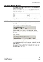
13.3  Activating / deactivating alarm lines (access code) 


An alarm line access code can be used to prevent unauthorised persons switching 
an individual alarm line or all the alarm lines to active or inactive. 


The value ‘0000’ means that changes can be made without having to input an 
access code. 

Any other 4-digit value activates the access code as soon as the 

OK 

button has 

been clicked to confirm. 

The following functions are protected by the access code: 

1. 

Changes to alarm status (active/inactive) of the individual alarm lines. 
Entry of digits ‘xxx’, function key ‘Alarm+’ 
Entry of digits ‘xxx’, function key ‘Alarm-’ 

2. 

Entering or changing monitor cycles 
Entry of digits ‘xxx’, function key ‘Zyk.Kx+’ 
Entry of digits ‘xxx’, function key ‘Zyk.Kx-’ 

Содержание SIMATRIX

Страница 1: ...Building Technologies Fire Safety Security Products SIMATRIX Programming manual V 2 70 ...

Страница 2: ...ne unsere vorgängige schriftliche Ermächtigung ganz oder teilweise Dritten zugänglich machen oder außerhalb des Zweckes verwenden zu dem es ihm übergeben worden ist We reserve all rights in this document and in the subject thereof By acceptance of the document the recipient acknowledges these rights and undertakes not to publish the document nor the subject thereof in full or in part nor to make t...

Страница 3: ...9 2 1 3 2 Interface parameters 19 2 1 4 IP address 19 2 2 Exit 19 2 3 Saving parameters to a data carrier 19 2 4 Creating a parameter file from a copy 20 2 5 Loading parameters from a data carrier 20 2 6 Printer 20 2 7 PIN code 21 2 8 Help 22 2 9 Printing parameter settings 22 2 10 System reset 22 3 Basic parameters 23 4 User display information 26 5 Image switching behaviour 28 5 1 Representation...

Страница 4: ... configuration 71 10 2 Basic time setting for the automatic Timer Reset 72 10 3 Defining the time interval for alarm zones 72 11 Selecting an alarm line camera group 73 11 1 Alarm line camera group x 73 11 2 Cameras in the group and alarm positioning 75 12 Alarm image switching 76 12 1 Choose a monitor group 76 12 2 Alarm configuration screen 77 12 2 1 Reset dialogue 78 12 2 2 Setting alarm image ...

Страница 5: ... 15 4 TELEMAT SISTORE NT LMS index card 95 15 4 1 TELEMAT MD MTD to SIMATRIX SYS 648 NEO 95 15 4 2 SISTORE NT to SIMATRIX SYS 648 NEO not with NEO V2 98 15 4 3 LMS to SIMATRIX SYS 648 164 NEO NEO V2 100 15 4 4 External computer to an SIMATRIX SYS 648 164 NEO NEO V2 104 15 4 5 IVM NT RS485 to SIMATRIX SYS 648 164 NEO NEO V2 106 15 5 Indicator lamp tableaus not with NEO V2 108 16 Remote control and ...

Страница 6: ......

Страница 7: ...red by the SIMATRIX video matrix systems from the Windows configuration screen on your PC The software also allows you to back up your system configuration and edit camera texts As the description that follows applies to all the video matrix system types they are globally referred to as SIMATRIX Only when there are differences between the systems are they referred to explicitly by their model desi...

Страница 8: ... your computer 1 Insert the CD Î Now the setup starts automatically if not then please start setup exe on the CD 2 If you don t want start the program via Start Programs drag the VM_WIN8 EXE program icon from the installation directory to the desktop You can change the name if required to VM_WIN8 for example 3 Double click the program icon to start the programming software 4 When starting program ...

Страница 9: ...COM2 connector 25 pin Sub D socket on the SIMATRIX SYS control unit 3 If you have a SIMATRIX NEO SIMATRIX NEO V2 SIMATRIX 648 or SIMATRIX 164 you also connect the cable to the COM2 interface 9 pin Sub D plug Fig 2 shows the typical connection cable configuration between the SIMATRIX SYS and a computer PC AT using a 9 pin or 25 pin serial interface Sub D socket Fig 3 shows the typical connection ca...

Страница 10: ... with a standard patchcabel or a switch For further instruction please look at General functions see section 2 1 4 Set up 1 4 1 Parameter settings at delivery The following alarm programs are loaded for the various types of device SIMATRIX SYS Alarm program ALARM2 dat SIMATRIX NEO Alarm program ALARM_N dat SIMATRIX NEO V2 Alarm program ALARM2_N2 dat SIMATRIX 648 Alarm program ALARM2_6 dat SIMATRIX...

Страница 11: ...setting up special independently enabled interfaces SIMATRIX Relevant programs SIMATRIX SYS BASIS dat and ALARMx dat SIMATRIX NEO BASIS_N dat and ALARMx_N dat SIMATRIX 648 BASIS_6 dat and ALARMx_6 dat SIMATRIX 164 BASIS_1 dat and ALARMx_1 dat To ensure the SIMATRIX 648 164 recognises the keyboards connected to the system the number of keyboards must be set as a permanent parameter in the Basic par...

Страница 12: ...box should be activated if the SIMATRIX is to be programmed via a client vm_win8 exe installed on the client It is also necessary to activate the VideoAPI checkbox if the IVM NT Client application will run in parallel Server This checkbox should be activated if the SIMATRIX is to be programmed via a server vm_win8 exe installed on the server It is also necessary to activate the VideoAPI checkbox i...

Страница 13: ...ou are in fact loading the parameters from the file in the SIMATRIX Changes are transferred to the SIMATRIX immediately but not automatically saved to the file You can then save the parameters to the hard disk or a floppy see section 2 3 1 7 Off line operation If the program is unable to find a viable connection to the video matrix it will automatically switch to off line operation You can also se...

Страница 14: ...on in the Programming the keyboards dialogue screen see section 6 4 In the On screen display dialogue screen see section 4 you must allocate a monitor to each keyboard or you will not be able to view any data you enter using the device 5 If you use camera head drives CDC define which keyboard controls which camera in the Camera control unit CDC dialogue screen see section 9 The allocation of camer...

Страница 15: ...ormally closed for each detection group in the Alarm lines camera groups dialogue screen see section 11 You can set the appropriate camera group here if more than one camera is to be switched when an alarm is triggered 3 Now use the Alarm switching configuration dialogue screen see section 12 to determine which monitors switch alarm images and how switching takes place 4 In the Alarm reset mode an...

Страница 16: ...ram options This dialogue window can be opened using the Options button Fig 6 Program options 2 1 1 Choice of language Select the required user language z Espagnol z Deutsch z English z Français Select by clicking a language When working on line the video matrix will switch to your choice of language monitor fade ins ...

Страница 17: ...r 2 Translate the text to the desired language Make sure you use the same amount of characters for the text 3 Replace the 9 in the current text by the designation for the language you want to appear in language selection dialogue screen Caution Make sure you neither add nor delete lines 4 Open the flag file Ger_flg bmp and save it as Def_flg bmp 5 The flag can now be changed at will This newly cre...

Страница 18: ...se of the SIMATRIX 164 keyboard no O membrane keypad is enabled Fig 8 Function keys on the front keypad Function keys F1 F4 can be freely programmed see section Keyboard layout IVM The LMS module is connected to the COM2 serial interface port in the case of the SIMATRIX 164 see the Ports on the video matrix dialogue screen Fig 9 The interfaces of the video matrix SIMATRIX 164 LMS ...

Страница 19: ...e SIMATRIX will display the chosen baud rate upon start up The PC to which the SIMATRIX is connected must be set to the same baud rate and other interface parameters as the SIMATRIX The following parameters for communication with the SIMATRIX can be enabled and assigned to the active interface in the programming PC z 8 2 E z 8 1 N z 8 1 E 2 1 4 IP address Here is shown the IP address of SIMATRIX N...

Страница 20: ...e transferred immediately to the SIMATRIX the parameter file remains unaffected 3 If you want to save the new parameters afterwards you must use the Save button to write your changes to file 2 5 Loading parameters from a data carrier The Load button allows you to load parameter files from the CD delivered with the unit dat or any other kind of parameter files held on a different data carrier If yo...

Страница 21: ...t then enter the PIN code again if you want to change parameter settings The PIN code itself is set in a different program For security reasons an external program vm_pin exe is used to set the PIN code The following PIN code is active when the program is supplied initially 12345 If you have used the external program vm_pin exe to set the PIN code you must delete this file from the hard disk after...

Страница 22: ...g the system configuration and identifying the cause of errors The standard format is DIN A4 Click the box to select the required list and confirm by clicking OK There are listings available for the basic parameters CDC configuration alarm lines camera groups and the individual camera label texts The current date and time appear on each printed listing Fig 11 Printing parameter settings 2 10 Syste...

Страница 23: ... where you can select a camera or a monitor only those cameras or monitors entered in the Basic Parameters screen will appear in the selection list Fig 12 Basic parameters Maximum number of system cameras Enter the total number of cameras or inputs you intend to use in the system here When you activate the Transfer to all outputs option the Image switching parameters dialogue screen will display t...

Страница 24: ... will be ignored if you tick the box here Box not ticked the signal failure test is not ignored If a camera registers as unavailable it will not switch in during manual switching An error message No Signal indicates that the camera is not available Box ticked the signal failure test is ignored Ticking the box deactivates automatic signal failure recognition This means that inputs without a signal ...

Страница 25: ...he master alarm relay in the event of the collective failure signal It is possible to exclude unused channels Fig 13 Selecting the input for setting the master relay if signal is lost The window shows all selected inputs which are included in the collective signal status The ticked boxes next to the input numbers indicate inputs where a signal is included Unticked boxes next to the input numbers i...

Страница 26: ...lay the data entered by the user It is also possible to fade in the date time and the status of the alarm areas Fig 14 User display information Display mode You can select the information for display here when the user keys data in on a keyboard z Keyboard input only z Keyboard input and clock z Keyboard input clock and alarm zones The display on the monitor will react as soon as the user presses ...

Страница 27: ...emoved after x seconds The start up message that follows a power on reset or system reset which appears on all the monitors connected to the system can be erased after a preset period of time If this setting has not been activated the start up message will remain on display until the first image appears z Status message removed after x seconds z Automatic start up message erasure not enabled The s...

Страница 28: ...layed is restricted by the data entered in the Basic Parameters dialogue screen Alternatively you can also select Show from monitor x This feature is intended to display monitor strings exceeding the limits of a 16 monitor group more clearly The Sub station button allows you to set sub station parameters 5 1 Representation of image switching behaviour The following window appears when you have sel...

Страница 29: ... will appear above the monitor icon here no 4 Display options for video switching modes z Automatic picture cycle enabled If an automatic picture cycle has been enabled a circular sequence icon with two arrowheads and a camera icon will appear in the corresponding monitor icon z An A in the camera icon indicates that the Auto start after power on option is active see section 5 1 2 2 z Monitor stri...

Страница 30: ...w If you are working in the on line mode the parameters will not come into effect until you have confirmed them with OK to send the parameters to the video matrix Click Cancel to keep the original parameter settings 5 1 1 Assigning keyboards The Assign keyboard button opens the On screen display dialogue screen see section 4 5 1 2 Setting video switching mode parameters for monitor x Fig 19 Settin...

Страница 31: ... monitor string has been set in Switching to more than one monitor previously The maximum length of the string is 8 monitors Switching to monitors x to y and 1 image per switching operation Group You can enable group switching by selecting Group if a number of cameras are to be switched simultaneously In this case any input via the keyboard using the digit keys will be interpreted as a group numbe...

Страница 32: ...ut You must enter the highest and lowest camera Any cameras that fall outside this series are not switchable This limitation only applies to individual manual switching This parameter is ignored in the case of manual group switching or image cycle switching The number of cameras is also limited by the relevant basic parameter see section 3 5 1 2 2 Automatic picture cycle Fig 21 Automatis picture s...

Страница 33: ...ing mode also only displays single images in turn however each image that has already been displayed is moved on one step in the monitor string This function can only be activated if the length of the monitor string has been set in Switching to more than one monitor previously e g switching to monitors 1 4 The length of the string is limited to 8 monitors Switching to monitors x to y and 1 image p...

Страница 34: ...g operation This is important for group switching You can indicate here which images from the camera group should be switched Only operating mode 1 Camera number can be used with the preset sequence see section 8 2 Interval time in sec This setting allows you to define how long in seconds an image or a camera group should be displayed before being overwritten Only inputs with signal If this option...

Страница 35: ...his dialogue screen is only of any significance if sub stations are connected to the SIMATRIX This window shows the sub stations that have been parameterised see section 5 2 2 These are indicated by a green screen Fig 22 Sub station configuration The Central button open the Central dialogue screen see section 5 2 1 the SUB x buttons open the relevant dialogue screens for each sub station 5 2 1 Cen...

Страница 36: ...onnected to the main video matrix by four video cables four channels these outputs are automatically designated outputs 1 to 4 on sub station 1 You must now indicate the main video matrix inputs to which these four channels are connected In principle there are no restrictions on which inputs on the main video matrix are used If you have connected sub station outputs 1 to 4 to inputs 5 to 8 on the ...

Страница 37: ...s can be user defined Macros only with NEO V2 Opens the macro definition screen There can be defined up to 32 macros with up to 48 functions and sub functions for each macro This button is only available with NEO V2 With the other SIMATRIX types the macros are generated by keyboard comand sequences 6 1 Keyboard layout IVM If IVM operator stations are used open the Video matrix interfaces dialogue ...

Страница 38: ... layout of keyboard x IVM 6 2 Connecting CKA 48 32 keyboards Fig 27 Selection CKAxx keyboard This notifies the SIMATRIX and the parameterisation program which keyboards in the system are type CKA 48 32 units A modified version of the Keyboard layout of keyboard x dialogue screen is required to set parameters ...

Страница 39: ...Fig 29 Keyboard layout for SUT 48 keyboard 1 1 SUT 48 extension The SUT 48 keyboards have 32 freely programmable keys There are certain limitations that apply to programming the 8 highlighted keys for the SUT 48 extension When you open the Programming the keyboards dialogue screen for the additional SUT 48 keys only the available key setting options will appear ...

Страница 40: ...yout shown corresponds to the current key allocation for this keyboard in the example above standard layout for keyboard 1 The current functionality is displayed in the key icons in each case Placing the mouse pointer on a key opens a small pop up box which briefly describes the programmed functionality The Standard button restores key allocation to standard settings Clicking the Print button prin...

Страница 41: ...oard 1 Input output function category 5 Various functions 2 Automatic picture cycle function category 6 Relay function category 3 Alarm processing function category 7 Digit keys function category 4 Camera control function category 8 Display window Current parameter settings for the selected functions and extra parameters Each key can be allocated a function from any one of the seven function categ...

Страница 42: ...max 255 using the digit keys then press the function key never in reverse order For example Switching camera 15 to monitor 7 1 Program a key with the Input preselect function without entering the number of the video input and another key with the Output function without setting the number of the video output 2 Now enter 1 and 5 using the digit keys and press the Input preselect key 3 Now enter 7 u...

Страница 43: ...he function key Procedure at the keyboard Output This function allows selection of the video output to which you want to switch the image signal The square grey button in the display window can be used to select one of the two switching options described below MON z Switching to any monitor Enter the number of the desired video output at the keyboard using the digit keys then press the key that ha...

Страница 44: ...he digit keys then press the key that has been allocated this function x y z The numbers of the video input and output are fixed Permanently program the input and output using the two scroll bars to allow full switching at a single press of a button 6 4 2 Automatic picture cycle function category Fig 34 Automatic picture cycle function category Image interval time Each time this function is activa...

Страница 45: ...r using the digit keys 4 Execute the image interval time function Tim Camera release This function allows the user to enable his choice of video input for an automatic picture cycle The video output can either be selected at the keyboard using the digit keys or selected in the display window using the scroll bar Zyk K 1 Preselect the camera using the Input preselect key 2 Using the digit keys ente...

Страница 46: ... digit keys This means that either the current camera can be disabled for the preset output at a press of a button or you can enter the number of the camera you want to disable using the digit keys 4 Then execute the Input preselect function 5 And finally execute the ZyK x function Cycle start This function starts an automatic picture cycle on any monitor or a programmed monitor Start z Image sequ...

Страница 47: ...ow The sequence can be stopped at the keyboard at the press of a button You can also use this function to stop a preset sequence see section 8 2 6 4 3 Alarm processing function category Fig 35 Alarm processing Alarm reset This function allows displayed alarm images to be deleted Reset z Deleting all alarm images in the system The scroll bar in the display window must be set to its initial position...

Страница 48: ... the access code referred to above see section 13 4 Alarm line inactive This function deactivates an alarm line in a similar way to the Alarm line camera group dialogue screen Alarm line deactivation remains in force until the next system reset Alarm handling can be protected by an access code see section 13 3 1 Enter the alarm line number using the digit keys and press this function key The key h...

Страница 49: ...ive if the alarm zone is manually inactive and the preset switching time lies in the past SISTORE NT not available with NEO V2 The scroll bar can be used to assign the following functions to the function key z Stop display z Store alarm sequence z Stop image recording z Start image recording z Show live image z Show stored image z Show last or selected image sequence z Display z Play back z Switch...

Страница 50: ...sign various camera lens control functions to different keys here This includes zoom and focus control in the case of mechanically driven lenses Lens driver commands set using the scroll bar z Zoom Tele z Zoom Wide z Focus Near z Focus Far z Electronic Zoom for remote digital cameras z Electronic Zoom for remote digital cameras Remote Digital Camera It is possible to assign various remote digital ...

Страница 51: ...g the arrow keys z Store the camera position to memory MEM Store the current camera position under a position number Enter the position number using the digit keys and store by pressing this function key Scroll bar in its initial position Store the camera position as a permanently programmed position number Set the position number using the scroll bar z Call up a camera position POS Call up a prog...

Страница 52: ...ub station function category Fig 37 Sub station Sub station This function key switches images from a camera that is connected to a sub station When switching a camera connected to a sub station the number of the sub station must also be indicated when switching takes place 1 Preselect the sub station using the digit keys and then activate the Sub station function key Scroll bar in its initial posi...

Страница 53: ...e scroll bar in the display window in the left hand position Enter the macro number at the keyboard 1 2 3 or 4 then press the key that has been assigned the Macro function z Recording macros not with NEO V2 1 To start recording Use the digit keys to enter the number of the macro 100 at the keyboard i e 101 102 103 or 104 2 Press the key that has been assigned the Macro function 3 Now execute the m...

Страница 54: ...ected by preselecting the desired relay number The position of the scroll bar has no effect in that case Port This key function allows any data bit of the 8 bit parallel port to be set to COM2 Program the control outputs D0 D7 using the scroll bar Display window options z permanent switching a permanent signal condition z toggling a signal changes the condition and this condition is then maintaine...

Страница 55: ...arm master relay can also be cleared automatically in the event of an alarm This is parameterised in the Basic alarm parameters dialogue screen 6 4 7 Digit keys function category Fig 39 Number keys Normally each keyboard has a numerical key pad 0 to 9 as most functions require an input via the digit keys 1 The key to be programmed can be allocated a digit in the range 0 to 9 to allow the entry of ...

Страница 56: ...unctions and subfunctions can be defined Fig 41 Macro selection Each of the 32 macros can contain up to 48 functions with subfunctions The first macro can be defined as startmacro It is exectued then after power on or reset If a contact is defined the macro starts after triggering this contact Fig 42 Macro function definition ...

Страница 57: ...tions can be defined One single macro can contain up to 48 functions If mor functions are neede it is possible to call another macro at the end of the first macro The definition of the macro functions is compatible to the parametrization of the keyboard keys See also chapter 6 3 1 Fig 43 Parametrization of macro functions ...

Страница 58: ...amera text A user defined text can be entered here for every camera in the system This text will then be superimposed on the camera image when it is switched if the Display camera text option has been activated in the Setting video mode switching parameters for monitor x dialogue screen see section 5 1 2 3 The text is displayed in 12 lines of 24 characters each No more than 100 characters in total...

Страница 59: ...xt for camera 3 7 3 Text field offset With this option the position of the text field within the camera image can be defined The separate value fields for the horizontal H and vertical V positions use the top left of the image as a datum point 7 4 Text field offset for CDC When controlling a CDC using a keyboard the corresponding control command is faded into the camera image To prevent interferen...

Страница 60: ...tings to a range of cameras starting from camera x start value up to the desired camera number last camera Press the Start key to copy the text Completely new This copies the text and offset settings to the selected camera numbers Only offset new This only copies the offset settings to the selected camera numbers 7 6 Switching to output x This function allows immediate switching of the text displa...

Страница 61: ...red in the Setting video mode switching parameters for monitor x dialogue screen see section 5 1 2 There is a distinction between A monitor cycle see section 8 1 A monitor cycle can include all the cameras that are present in the system The set cameras are switched in ascending order A preset sequence see section 8 2 A preset sequence includes a maximum of 32 cameras The set cameras are switched i...

Страница 62: ... cycle the cameras are switched in ascending input number order e g 1 3 4 8 12 etc in this case the sequence consists of cameras 1 to 16 on monitor 1 Fig 47 Monitor cycle on monitor x Tick the boxes here for all the cameras you wish to include in the monitor cycle Remember that the cameras are always switched in ascending input number order Further monitor cycle parameter settings can be entered i...

Страница 63: ...or cycle 1 Enter the monitor number 2 Press the Cycle start key To stop a monitor cycle 1 Enter the monitor number 2 Press the Cycle stop key Higher priority image switching also stops the sequence Alternatively it is also possible to permanently allocate the Cycle start and Cycle stop keys to a monitor Entry of the monitor number is not then required 8 2 Preset sequence no x Fig 48 Preset sequenc...

Страница 64: ...t field if a camera is connected to a sub station Starting a preset sequence using a keyboard Starting and stopping a monitor cycle requires the Cycle start Cycle stop and Input preselect keys on the keyboard These keys are programmed in the Programming keyboards dialogue screen see section 6 4 To start a preset sequence 1 Enter the table number using the digit keys 2 Press the Input preselect key...

Страница 65: ...ard x controls all cameras on monitor y This mode allows automatic control of the camera that is currently switched to a monitor permanently assigned to the keyboard when a camera is switched manually or as a result of an alarm This option is the most user friendly control mode and offers the greatest security Monitor parameters can be programmed using the arrow keys z Keyboard x controls the last...

Страница 66: ...yboard which transmits the last control command The parameter settings of keyboards T11 T13 are relevant for the serial interfaces for the connection of external computers such as IVM These keyboards can also be allocated control priorities 9 3 Maintaining control priority precedence When two keyboards attempt to gain access simultaneously the keyboard with the higher priority takes precedence A t...

Страница 67: ...ing the keyboard see the operating manual z No return to the default position Set using the arrow keys z Return to the default position after x seconds Set using the arrow keys 9 5 Camera selection The Relation Camera CDC button in the Camera head control dialogue window opens the Choose a camera from dialogue screen Each pan tilt camera that is fitted with a CDC must be allocated an unambiguous C...

Страница 68: ...ress allocation to a camera Fig 51 Relationship between camera and CDC z Input number x relates to CDC address A CDC address can be allocated to each camera in the system All the CDCs and interfaces in the system must have their own unambiguous address This address is set in the device itself In the standard system address allocation is 1 1 the camera number is the same as the address It is only n...

Страница 69: ...drive In that case all the commands destined for the camera head address will be always be transmitted as electronic code z Position Activate this option if the CDC allows position control z Variable speed Activate this option if the SIMATRIX has to send variable speed commands for camera movement If this option is not activated the SIMATRIX will only transmit fixed speed commands meaning that the...

Страница 70: ...st alarm line and secondly how many alarm lines are used These alarm lines will then be correctly allocated if you have connected them in sequence from first to last to the alarm line inputs on the SIMATRIX starting with the first input for alarm lines setting for 1st alarm line at The Alarm line camera groups dialogue screen allows the setting of further parameters for each individual alarm line ...

Страница 71: ...meters for the UART MX 16 interface card S I O 0 to S I O 15 correspond to I O terminal strip 0 15 UART MX 16 0 no 1 to UART MX 16 0 no 16 The AS32MX and A32MX alarm cards each have 32 alarm inputs Setting parameters for the AS32MX alarm card S I O 16 to S I O 47 correspond to AS32MX 1 no 1 to AS32MX 1 no 32 S I O 48 to S I O 79 correspond to AS32MX 2 no 1 to AS32MX 2 no 32 Setting parameters for ...

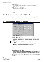
Страница 72: ... immediate effect if the start time for the day in question already lies in the past The setting will take effect on the following day at the earliest To test the setting set the start time to a time that is just a few minutes in the future For example You want to set and test a time interval of 17 00 to 24 00 It is already 17 10 when you enter the setting The time interval would normally only com...

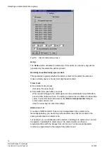
Страница 73: ...defined here see section 11 1 can also be switched manually and totally independently of an alarm if group switching has been enabled in the manual switching field in the Setting video mode switching parameters for monitor x dialogue screen see section 15 1 2 Fig 55 Alarm lines camera group Use the Alarm lines camera groups button and then click a number button to open the Alarm line camera group ...

Страница 74: ...ggers the alarm signal can be automatically turned off after a period of time that is set here The setting is entered as a multiple of a basic time value You set this basic time value in the Basic alarm parameter dialogue screen see section 10 2 Use the arrow keys to enter the setting Alarm zone 1 8 A number of different alarm lines can be amalgamated into an alarm zone Generally speaking you woul...

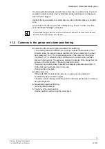
Страница 75: ...itching The camera groups are defined here A group consists of a maximum of four cameras Enter the desired camera numbers for the four cameras in the group here cameras 1 to 4 The numerical sequence of the cameras in the group cameras 1 to 4 is relevant in that switching within a monitor string will take place in this sequence The sequence starts with a display of the image from the camera on the ...

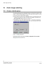
Страница 76: ...o set up for alarm image switching z No more than 16 monitors can be displayed at once The selection shown here is limited to the maximum number of monitors in the system as entered in the Basic parameters dialogue screen see section 3 z Alternatively you can select Show from monitor This feature is designed to display monitor strings exceeding the limits of a 16 monitor group more clearly Fig 57 ...

Страница 77: ...alogue screen see section 13 Fig 58 Alarm configuration screen This dialogue screen presents a graphical display of the alarm configuration of the video outputs In principle the display is exactly as shown in the Video mode configuration dialogue screen That screen displays normal video image switching behaviour as opposed to the alarm image switching behaviour that is shown here Fig 59 Representa...

Страница 78: ...nabled for alarm image switching are also displayed in the same way Alarm image switching only needs to be enabled for the alarm master monitor not for the slave monitors The alarm master monitor is also shown in the Video mode configuration dialogue screen see section 5 1 z Representation of the parameter settings as entered in the Alarm reset mode and stack alarm handling dialogue screen see sec...

Страница 79: ...p the original parameter settings Fig 60 Setting alarm image switching mode parameters on output x This dialogue screen allows you to set the alarm switching mode for a given monitor Any settings you enter or change here will only apply to the monitor concerned This dialogue screen allows parameterisation of a monitor s image switching response You can select one of three different operating modes...

Страница 80: ...left to right to each monitor in turn but displayed alongside each other in sequence So the first alarm image appears on the first monitor in the string the second alarm image on the second monitor in the string etc If images from camera groups are to be switched the leading monitor in the subgroup must be programmed as the alarm monitor string and group size but not alarm monitor Alarm image swit...

Страница 81: ...roup will be displayed etc As a group can include no more than four cameras see section 11 2 the maximum number of images per alarm event is also four Set using the arrow keys Alarm zone You can set the alarm zones here by selecting any of the zones 8 maximum whose alarm events are to be switched to the monitor in question For example Only alarm zone 1 is active Only alarms generated by the alarm ...

Страница 82: ... monitors in the string The alarm images are correspondingly cleared from monitors 1 n Set using the arrow keys If serial switching is active the group will be always be cleared When a reset is executed on the alarm monitor or the lead group monitor Alarm image behaviour z After alarm reset After an alarm has been cleared two different parameters can be set using the switch The alarm image display...

Страница 83: ...different Reset operating modes z Manual reset z Automatic reset z Stack alarm handling Manual reset In this mode you can clear alarms in one of the following ways z using the Alarm reset key on the keyboard z By manually overwriting the alarm image only possible if the Alarm images can be overwritten manually option is active z By switching a new image or z Keying in x and MON z The alarm will cl...

Страница 84: ... allocated to a monitor It is generally recommended that a video recorder is also connected to the monitor Set the monitor parameters using the arrow keys z Hold time alarm picture cycle x seconds Enter the display hold time for the alarm image sequence in seconds max 99 seconds Use the arrow keys to enter the value 13 3 Activating deactivating alarm lines access code An alarm line access code can...

Страница 85: ...eyboard to set alarm lines to active inactive using an access code The following keys must be programmed on the keyboard Alarm line active alarm line inactive and the digit keys 1 Use the digit keys to enter the first two digits of the access code 2 Press the Alarm line active or Alarm line inactive key 3 Enter the third and fourth digits of the access code 4 Press the Alarm line active or Alarm l...

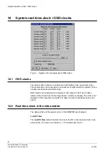
Страница 86: ...These overlays are described as OSD clocks OSD clocks can be allocated to a maximum of 8 outputs The H and V offset relates to the camera text of the image that is currently on display The clock is not displayed if the output has no signal The date can also be displayed as an extra option 14 2 Real time clock in the video matrix The date and time of the system clock in the SIMATRIX are displayed L...

Страница 87: ... is useful when the video matrix or the CPU card will be out of operation for an extended period This feature prevents premature battery discharge and the ensuing loss of settings With SIMATRIX NEO V2 this function is no longer necessary as the real time clock needs much less battery if the SIMATRIX is switched off 14 3 Switching between summer and winter time Defining system time as summer or win...

Страница 88: ...RS232 COM2 COM3 COM4 IVM NT RS485 COM2 LMS COM3 SISTORE NT COM2 COM3 COM4 TELEMAT COM4 External system connections to SIMATRIX 164 that are available as standard External systems Available COM connections IVM NT COM2 LMS COM2 External system connections to SIMATRIX SYS 648 that are available when enabled module External systems module Module ordering numbers see also PN Available COM connections S...

Страница 89: ...OM4 19200 8 E 2 TELEMAT COM4 9600 19200 8 E 2 TELEMAT parameterisation COM2 19200 8 E 2 SISTORE NT switch over control COM2 COM3 COM4 19200 8 E 2 SISTORE NT operation COM2 COM3 COM4 19200 8 E 2 LMS COM3 2400 8 N 1 GMA COM3 9600 7 E 1 External computer COM2 COM3 COM4 19200 8 E 2 IVM NT RS485 COM2 COM3 COM4 19200 8 E 2 IVM NT RS 232 COM2 19200 8 E 2 SIPORT COM3 9600 7 E 1 Connection from SIMATRIX 16...

Страница 90: ...he event of an alarm and in the event of camera failure An IVM PC or serial printer can be connected to the selected interface 15 1 2 Alarm picture storage via interfaces If required an external computer for storing alarm images can be connected to one of the three interfaces on the SIMATRIX 15 1 3 Serial printer on A serial printer for generating hard copy documentation can be connected to all th...

Страница 91: ... COM4 15 1 6 Keyboard on COM2 COM3 COM4 The SUT 48 and CKAxx10 keyboards can be connected directly to COM2 COM3 or COM4 in contrast to other keyboards Enter here whether and to which interface the keyboard is connected z No keyboard connected to COMx Set using the arrow keys z Keyboard with address x connected to COMx Set address x using the arrow keys In order to refresh the OSD on the monitor al...

Страница 92: ...ve interfaces dialogue screen 15 2 1 COM2 COM3 COM4 interface settings The interface settings must be configured for each interface used by selecting the desired values As standard COM1 should be set to a baud rate of 2400 baud as the devices connected to this port keyboards CDC are set to 2400 baud as standard COM2 to COM4 should be set as standard to a baud rate of 19k2 and a data format of 8 E ...

Страница 93: ...ng keyboards 15 2 3 Controlling a sub station using This dialogue screen is only of any significance if a sub station is connected to the SIMATRIX In the main matrix only SIMATRIX SYS NEO 648 Only one interface can be selected for sending commands to a sub station Select the serial interface which will be used to connect the sub station to the SIMATRIX In the sub station Address directed control i...

Страница 94: ...eo matrix 94 Siemens Building Technologies Fire Safety Security Products 06 2008 15 3 Telemetry Ports only with NEO V2 Fig 65 Telemetry Ports Here the protocol format and baudrate of each telemetry port can be defined ...

Страница 95: ... 15 4 1 TELEMAT MD MTD to SIMATRIX SYS 648 NEO with NEO V2 only the alarms from telemat are interpreted and used for camera switching Recommended parameter settings example extra parameterisation via COM2 The following standard parameter settings apply for the Messages keyboards index card fields in white boxes Fig 67 TELEMAT connection register Messages keyboards ...

Страница 96: ...u option Local control via Fig 68 TELEMAT MD MTD connection register COM1 4 control The following standard parameter settings apply for the TELEMAT SISTORE NT LMS index card fields in white boxes Fig 69 TELEMAT connection TELEMAT SISTORE NT LMS register TELEMAT is reset when system starts Select the checkbox if TELEMAT should also be reset when a system reset takes place COM2 with IVM TELEMAT cont...

Страница 97: ...channel is also switched between active inactive The SIMATRIX integrates TELEMAT alarms into normal alarm processing If an alarm originates from a TELEMAT it is converted to the corresponding alarm line and switched to screen TELEMAT modulation alarms are handled by the SIMATRIX in the same way as an alarm If the TELEMAT alarm is to be reset by the SIMATRIX no auto reset the alarm zone containing ...

Страница 98: ...ration by switching alarm zone 1 to active inactive From version VMx_9905 X12 on the TELEMAT can also be set to active inactive via alarm zone 1 timer settings 15 4 2 SISTORE NT to SIMATRIX SYS 648 NEO not with NEO V2 Recommended parameter settings example SISTORE NT to COM3 messaging operation Fig 70 SISTORE NT messaging operation TELEMAT SISTORE NT LMS The following standard parameter settings a...

Страница 99: ...ORE NT for message operation COM1 4 control The following standard parameter settings apply for the TELEMAT SISTORE NT LMS index card fields in white boxes Fig 73 Connecting SISTORE NT for message operation TELEMAT SISTORE NT LMS SISTORE camera switching commands sent by SISTORE NT SIMATRIX Select the checkbox for the SIMATRIX interface which will be used to send switching commands to the SISTORE ...

Страница 100: ... connection allows the SIMATRIX to be coupled as a subsystem within LMS Modular The following basic functions can be implemented using the LMS connection z Transmission of alarm signals to LMS z Video signal failures z Alarms Receiving control commands from LMS z Status request z Time alignment z Switching video inputs to video outputs z Activating and deactivating alarm lines z External alarms z ...

Страница 101: ...ire Safety Security Products 06 2008 The following standard parameter settings apply for the Messages keyboards index card fields in white boxes Fig 74 Connecting LMS to SIMATRIX SYS 648 Messages keyboards Fig 75 Connecting LMS to SIMATRIX 164 Messages keyboards ...

Страница 102: ...nologies Fire Safety Security Products 06 2008 The following standard parameter settings apply for the COM1 4 index card fields in white boxes Fig 76 Connecting LMS to SIMATRIX SYS 648 COM1 4 control Fig 77 Connecting LMS to SIMATRIX 164 COM1 4 control ...

Страница 103: ...fety Security Products 06 2008 The following standard parameter settings apply for the TELEMAT SISTORE NT LMS index card fields in white boxes Fig 78 Connecting LMS to SIMATRIX SYS 648 TELEMAT SISTORE NT LMS Fig 79 Connecting LMS to SIMATRIX 164 TELEMAT SISTORE NT LMS ...

Страница 104: ... subsystem within LMS Modular This is the COM2 interface in the case of the SIMATRIX 164 After setting interface parameters the system must be reset before the new settings will take effect 15 4 4 External computer to an SIMATRIX SYS 648 164 NEO NEO V2 Recommended parameter settings example external computer on COM2 see also alarm2_6 dat The following standard parameter settings apply for the Mess...

Страница 105: ...on of an external computer COM1 4 control If the external computer is connected via COM2 COM2 must be selected in menu option Local control via The following standard parameter settings apply for the TELEMAT SISTORE NT LMS index card fields in white boxes Fig 82 Connecting and external computer TELEMAT SISTORE NT LMS After setting interface parameters the system must be reset before the new settin...

Страница 106: ...ended parameter settings example IVM NT on COM2 see also ivm_nt dat The following standard parameter settings apply for the Messages keyboards index card fields in white boxes Fig 83 Connection of IVM NT Messages keyboards The following standard parameter settings apply for the COM1 4 index card fields in white boxes Fig 84 Connection of IVM NT COM1 4 control ...

Страница 107: ...standard parameter settings apply for the TELEMAT SISTORE NT LMS index card fields in white boxes Fig 85 Connecting IVM NT TELEMAT SISTORE NT LMS After setting interface parameters the system must be reset before the new settings will take effect Each device is supplied with the relevant device programming manual A dat file with typical settings is supplied with the SIMATRIX as standard This file ...

Страница 108: ...3 different camera conditions z Lamp tableau for alarm display z Lamp tableau for display of switched cameras z Lamp tableau for display of signal status Fig 86 Connection of lamp tableaus The hardware for the tableaus is no longer available in standard component form Use the arrow keys to indicate the lamp tableau address from which the lamp tableaus will be used each tableau contains 30 lamps ...

Страница 109: ...the interface Image display By entering the camera and monitor number and clicking the Switch on Button any camera can be switched to any monitor single image switching Ext alarm Any one of the alarms can be simulated here The effect is the same as when the corresponding alarm is triggered If set to do so for example an alarm image will be displayed Camera status Camera signal status request signa...

Страница 110: ...t has been triggered is shown in the event of an alarm ACK stands for Acknowledge and means acceptance of the transmitted data NAK stands for Negative Acknowledge and means non acceptance for example if the transmitted data is incorrect If more messages have been transmitted than can be displayed in the window the scroll bar on the right can be used to scroll through the window The Clear button de...

Страница 111: ...Fig 22 Sub station configuration 35 Fig 23 Central 35 Fig 24 Sub station x 36 Fig 25 Selecting a keyboard for programming 37 Fig 26 Keyboard layout of keyboard x IVM 38 Fig 27 Selection CKAxx keyboard 38 Fig 28 Keyboard CKA 3210 CKA 48xx 39 Fig 29 Keyboard layout for SUT 48 keyboard 1 39 Fig 30 Keyboard layout for CKAxx10 keyboards 40 Fig 31 Function keys on the front keypad SIMATRIX 164 41 Fig 32...

Страница 112: ...RE NT for message operation Messages keyboards 98 Fig 72 Connecting SISTORE NT for message operation COM1 4 control 99 Fig 73 Connecting SISTORE NT for message operation TELEMAT SISTORE NT LMS 99 Fig 74 Connecting LMS to SIMATRIX SYS 648 Messages keyboards 101 Fig 75 Connecting LMS to SIMATRIX 164 Messages keyboards 101 Fig 76 Connecting LMS to SIMATRIX SYS 648 COM1 4 control 102 Fig 77 Connecting...

Страница 113: ...Index of illustrations 113 Siemens Building Technologies Fire Safety Security Products 06 2008 ...

Страница 114: ...buildingtechnologies siemens com 2008 Copyright by Siemens Building Technologies AG Data and design subject to change without notice Supply subject to availability Printed in the Federal Republic of Germany on environment friendly chlorine free paper Document no A24205 A336 B445 Edition 16 06 2008 ...

Отзывы: