Creating a Program in OB1
4-7
STEP 7 Getting Started
A5E00171228-01
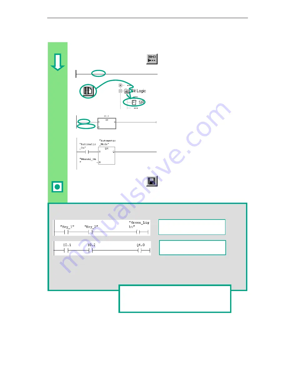
Programming a Memory Function in Ladder Logic
Select Network 2 and insert another
network.
Select the current path again.
Navigate in the Program Elements
catalog under Bit Logic until you
reach the SR element. Double-click to
insert the element.
Insert a normally open contact in front
of each of the inputs S and R.
Enter the following symbolic names for
the SR element:
Upper contact "Automatic_On"
Lower contact "Manual_On"
SR element "Automatic_Mode"
Save the block and close the window.
If you want to see the difference between absolute and symbolic addressing, deactivate the
menu command View > Display > Symbolic Representation.
You can change the line break for symbolic addressing in the LAD/STL/FBD program
window by using the menu command Options > Customize and then selecting "Width of
address field" in the "LAD/FBD" tab. Here you can set the line break between 10 and 24
characters.
Example:
Symbolic addressing in LAD
Example:
Absolute addressing in LAD
You can find more information under Help >
Contents in the topics "Programming Blocks,"
"Creating Logic Blocks," and "Editing Ladder
Instructions."
Содержание SIMATIC STEP 7 V5.2
Страница 4: ...Welcome to STEP 7 STEP 7 Getting Started iv A5E00171228 01 ...
Страница 12: ...Introduction to STEP 7 1 6 STEP 7 Getting Started A5E00171228 01 ...
Страница 22: ...Programming with Symbols 3 4 STEP 7 Getting Started A5E00171228 01 ...
Страница 60: ...Creating a Program with Function Blocks and Data Blocks 5 24 STEP 7 Getting Started A5E00171228 01 ...
Страница 76: ...Downloading and Debugging the Program 7 14 STEP 7 Getting Started A5E00171228 01 ...
Страница 88: ...Programming a Shared Data Block 9 4 STEP 7 Getting Started A5E00171228 01 ...
Страница 100: ...Programming a Multiple Instance 10 12 STEP 7 Getting Started A5E00171228 01 ...
Страница 110: ...Appendix A STEP 7 Getting Started A 2 A5E00171228 01 ...


