CPU 1517H-3 PN (6ES7517-3HP00-0AB0)
Equipment Manual, 11/2019, A5E42011886-AB
29
Interrupts, diagnostics, error messages and system
events
4
4.1
Status and error display of the CPU
The LED displays of the CPU are described below.
You can find more detailed information on "Interrupts" in the STEP 7 online help.
You can find additional information on the topic of "Diagnostics" and "System events" in the
Diagnostics (
http://support.automation.siemens.com/WW/view/en/59192926
) function
manual and in the system manual Redundant System S7-1500R/H
https://support.industry.siemens.com/cs/ww/en/view/109754833
You can find additional information on the topic of "Operating states and system states" as
well as various failure scenarios in the system manual for S7-1500R/H Redundant System
https://support.industry.siemens.com/cs/ww/en/view/109754833
LED display
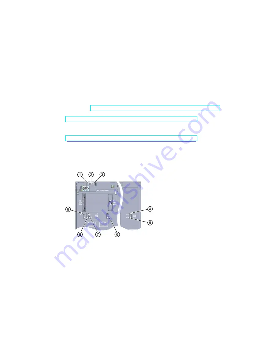
The figure below shows the LED displays of the CPU 1517H-3 PN.
①
RUN/STOP LED (yellow/green LED)
②
ERROR LED (red LED)
③
MAINT LED (yellow LED)
④
LINK RX/TX LED for port X3 P1 (yellow/green LED)
⑤
LINK RX/TX LED for port X4 P1 (yellow/green LED)
⑥
No function
⑦
LINK RX/TX LED for port X1 P1 (yellow/green LED)
⑧
LINK RX/TX LED for port X1 P2 (yellow/green LED)
⑨
LINK RX/TX LED for port X2 P1 (yellow/green LED)
Figure 4-1
LED display of the CPU 1517H-3 PN (without front panel)
Содержание SIMATIC S7-1500R/H
Страница 1: ...CPU 1517H 3 PN 6ES7517 3HP00 0AB0 ...


