


RF600 system planning
4.6 Guidelines for electromagnetic compatibility (EMC)
RF600
4-28
System Manual, 09/2005 Edition, J31069 D0171-U001-A0-7618,
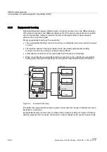
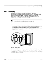
4.6.6
Equipotential bonding
Potential differences between different parts of a plant can arise due to the different design
of the plant components and different voltage levels. If the plant components are connected
across signal cables, transient currents flow across the signal cables. These transient
currents can corrupt the signals.
Proper equipotential bonding is thus essential.
•
The equipotential bonding conductor must have a sufficiently large cross section (at least
10 mm
2
).
•
The distance between the signal cable and the associated equipotential bonding
conductor must be as small as possible (antenna effect).
•
A fine-strand conductor must be used (better high-frequency conductivity).
•
When connecting the equipotential bonding conductors to the centralized equipotential
bonding strip, the power components and non-power components must be combined.
3RZHUVXSSO\
3/&
(8
(8
(8
'ULYH
,QFRUUHFW
,QFRUUHFW
&DELQHW
&DELQHW
Figure 4-8
Equipotential bonding
The better the equipotential bonding in a plant, the smaller the chance of interference due to
fluctuations in potential.
Equipotential bonding should not be confused with protective earthing of a plant. Protective
earthing prevents the occurrence of excessive contact voltages in the event of device faults.
Содержание SIMATIC RF660
Страница 5: ...Table of contents RF600 System Manual 09 2005 Edition J31069 D0171 U001 A0 7618 v ...
Страница 6: ......
Страница 16: ...System overview 3 1 RF System SIMATIC RF600 RF600 3 4 System Manual 09 2005 Edition J31069 D0171 U001 A0 7618 ...
Страница 66: ......
Страница 96: ...Appendix A 4 Training RF600 A 6 System Manual 09 2005 Edition J31069 D0171 U001 A0 7618 ...


