background image


RF600 system planning 


4.5 Regulations applicable to frequency bands 

RF600 
System Manual, 09/2005 Edition, J31069 D0171-U001-A0-7618,   

4-17


Channel assignment 


The UHF band from 865 to 868 MHz is subdivided into three sub bands: 


Sub bands 

Frequency range 

Output 

865.0 to 865.5 MHz 

0.1 W ERP 

865.6 to 867.6 MHz 

2,0 W ERP 

:

:

:

0+]

0+]

0+]

0+]


867.6 to 868.0 MHz 

0,5 W ERP 


Listen before talk 

With this technique, the reader checks whether a channel is assigned before transmission to 

prevent collisions. The reader will only transmit when a channel is free. The reader can 

transmit for up to ?? seconds on this channel and must then pause for at least ?? seconds or 

jump immediately to an unassigned channel on which it can transmit for a further ?? 

seconds. 
 

Regulations for frequency bands according to EN 300 220 (short range device) 

For those countries in which the RFID directive according to EN 302 208 has not yet been 

implemented, this alternative exists which is based on the older "Short range device" 

directive: 


EN 300 220 (short range device) 
Frequency range 

865.6 to 868 MHz 

Number of channels 

12 

Transmit power 

Max. 0.5 W ERP 

Duty cycle (frequency assignment period) 

10 % (6 min./h) 


Содержание SIMATIC RF660

Страница 1: ...ety Information 2 System overview 3 RF600 system planning 4 RF660R reader 5 Antennas 6 Transponder tags 7 Accessories 8 Appendix A SIMATIC RF600 RFID systems RF600 System Manual 09 2005 Edition J31069 D0171 U001 A0 7618 ...

Страница 2: ...tion Commissioning and operation of a device system may only be performed by qualified personnel Within the context of the safety notes in this documentation qualified persons are defined as persons who are authorized to commission ground and label devices systems and circuits in accordance with established safety practices and standards Prescribed Usage Note the following Warning This device may ...

Страница 3: ...0 4 2 7 Increasing the probability of identification for tags Antenna switching 4 11 4 3 Environmental conditions for transponders 4 12 4 3 1 Basic rules 4 12 4 4 The response of electromagnetic waves in the UHF band 4 13 4 4 1 The effect of reflections and interference 4 13 4 4 2 Influence of metals 4 14 4 4 3 Influence of liquids and non metallic substances 4 15 4 5 Regulations applicable to fre...

Страница 4: ...18 5 8 1 FCC information 5 18 5 8 2 Compliance distance for RF Exposure 5 18 6 Antennas 6 1 6 1 RF660A antenna 6 1 6 1 1 RF660A description 6 1 6 1 2 Application Planning 6 4 6 1 3 Installation Mounting 6 6 6 1 4 Connecting an antenna to a reader 6 9 6 1 5 Technical specifications 6 10 7 Transponder tags 7 1 7 1 Mode of operation of transponders 7 1 7 2 Transponder classes and generations 7 2 7 3 ...

Страница 5: ...Table of contents RF600 System Manual 09 2005 Edition J31069 D0171 U001 A0 7618 v ...

Страница 6: ......

Страница 7: ... error analyses Where this documentation is valid This documentation is valid for all supplied variations of the SIMATIC RF600 system and describes the state of delivery as of September 2005 Conventions The following terms abbreviations are used synonymously in this document Reader read write device write read device Tag transponder mobile data memory data carrier SmartLabel Communication module i...

Страница 8: ...0 1 2 System Manual 09 2005 Edition J31069 D0171 U001 A0 7618 Observance of installation guidelines The installation guidelines and safety instructions given in this documentation must be followed during commissioning and operation ...

Страница 9: ...nd operating the product system and with reference to statutory regulations System overview Overview of all RF identification systems system overview of SIMATIC RF600 RFID system planning Information about possible applications of SIMATIC RF600 support for application planning tools for finding suitable SIMATIC RF600 components Readers Description of readers which can be used for SIMATIC RF600 Ant...

Страница 10: ...Introduction 1 2 Navigating in the system manual RF600 1 4 System Manual 09 2005 Edition J31069 D0171 U001 A0 7618 ...

Страница 11: ...he admissibility of the installation in the designated environment please contact your service representative Caution Alterations to the devices are not permitted Failure to observe this requirement shall constitute a revocation of the radio equipment approval CE approval and manufacturer s warranty Repairs Repairs may only be carried out by authorized qualified personnel Warning Unauthorized open...

Страница 12: ...evice If you install other upgrades you may damage the system or violate the safety requirements and regulations for radio frequency interference suppression Contact your technical support team or your sales outlet to find out which system upgrades are suitable for installation Caution If you cause system defects by installing or exchanging system expansion devices the warranty becomes void ...

Страница 13: ...enerate the receiving department transaction for the ERP system At the same time the delivery can be automatically checked for correctness and completeness prior to storage by means of the electronic delivery list QWHUQHW 1 WKHUQHW 352 86 WKHUQHW 5 DWD DFTXLVLWLRQ OHYHO 53 QWHUSULVH 5HVRXUFH 3ODQQLQJ b6 0b 6XSSO KDLQ 0DQDJHPHQW 0 6 0DQXIDFWXULQJ HFXWLRQ 6 VWHP 6 0 7 7 UDPHZRUN 5 5 UHDGHU ZLWK VHSD...

Страница 14: ...ogistics and distribution departments A small data medium referred to as SmartLabel or tag is adhered to every item package or palette and contains all important information The data medium receives the power it requires via an antenna which is also used for data transmission Equipped with a rugged casing to the high IP 65 degree of protection and suitable for use over a wide range of temperatures...

Страница 15: ...ansmission frequency 865 868 MHz Europe 902 928 MHz USA Read write distance Europe 3 5 m USA 4 m Data carrier tags Memory Up to 2048 bits Type Smart Labels Container tag available soon Heat resistant data medium available soon Standards EPCglobal Class 1 Gen 2 ISO 18000 6B Software Data Manager PC software for Configuration and diagnostics Interfacing to IT systems Configuration software PC softwa...

Страница 16: ...System overview 3 1 RF System SIMATIC RF600 RF600 3 4 System Manual 09 2005 Edition J31069 D0171 U001 A0 7618 ...

Страница 17: ...1 A0 7618 4 1 RF600 system planning 4 4 1 Overview You should observe the following criteria for implementation planning Antenna configurations Environmental conditions for transponders The response of electromagnetic waves in the UHF band EMC directives ...

Страница 18: ...ows an example of a portal configuration The antenna are positioned at the height at which the tags are expected which are to be identified The maximum width of the portal that is recommended for reliable operation is 4 m The diagram shows a configuration with two antennas Up to four antennas can be used depending on the local conditions 5HDGHU QWHQQH 7DJ DGHUDPSH Figure 4 1 Typical gate configura...

Страница 19: ...arrangement of antennas is appropriate when the tags to be read are only located on one side of the items to be identified e g when palettes are to be identified on which the tags to be read must be on a prespecified side Tag Antenna configuration 2 Description application areas Preferred application In the identification of goods in loading portals The tag is located in the field of radiation of ...

Страница 20: ...s in loading portals Similar to configuration 2 but with additional reading reliability when the tag is at an angle to the vertical Tag Antenna configuration 4 Description application areas Preferred application In the identification of goods in loading portals The tag is located in the field of radiation of all four antennas so the tag position can vary more than in configuration 2 for reliable t...

Страница 21: ...r antennas at separate locations so the tag position is not critical Tag Antenna configuration 6 Description application areas This tunnel configuration is suitable for conveyor belt applications The goods with the tags to be read are moving forwards on a conveyor belt but the alignment of the tags relative to the antennas is not clearly defined One of the antenna is located on the floor and radia...

Страница 22: ... the antenna of the reader affects the reading range For maximum performance and to achieve the maximum reading range the tag antenna should therefore be aligned in parallel with the reader antenna Parallel tag alignment Large reading range Maximum probability of identification of tags Perpendicular tag alignment Minimal reading range Minimum probability of identification of tags ...

Страница 23: ...iagram shows the specified minimum and maximum spacings for mounting antennas A minimum spacing of 50 cm is necessary between the antenna and liquids or metals The distance between the antenna and the floor should also be at least 50 cm PLQ FP PLQ FP ุ 0HWDO UDFN LTXLG Figure 4 2 Distance to the environment The distance between two antennas mounted alongside each other or one above the other shoul...

Страница 24: ...n J31069 D0171 U001 A0 7618 FP Figure 4 3 Antennas mounted adjacently horizontally or vertically For a portal configuration the distance between two antennas that are connected to the same reader is up to 3 5 m in Europe or 4 m in the USA XURSH PD P 86 PD P Figure 4 4 Portal configuration ...

Страница 25: ...is a danger that RFID tags can also be read by other readers It must be ensured that the tag can only be identified by the appropriate reader Technical faults between readers can then only occur when they transmit on the same channel i e in the same frequency range of a frequency band To prevent this the RF660R reader uses the Listen before talk technique in Europe or frequency hopping between man...

Страница 26: ... the tag antenna the larger the power input area and therefore the larger the reading range Absorption factor of the materials The higher the absorption of the surrounding material the smaller the reading range Antenna amplification The bigger the antenna amplification the larger the reading range Production quality of the tag The better the tag has been matched to the operating frequencies during...

Страница 27: ...is receiving signals from further tags the system continues to transmit on the same transmit antenna until all responding tags have been identified Subsequently or if no tags respond the system activates another antenna as the transmit antenna After all the antenna have transmitted at least once or when the settling time is excessively long the reader activates frequency hopping in the USA or chan...

Страница 28: ...tly on metal surfaces or on containers of liquid For physical reasons a minimum distance must be maintained between the tag antenna and conductive material A minimum distance of 5 cm is recommended The tag function is improved with greater distances between 5 and 20 cm The best performance is achieved when the tag is mounted on a non conductive material such as plastic or wood Exception Tags that ...

Страница 29: ...result in waves being extinguished which causes holes in reader coverage Reflections can also be beneficial when they cause electromagnetic waves to be routed around objects to a certain extent deflection This can increase the reading probability Due to these electromagnetic characteristics it is extremely difficult in the multiple reflection environment that is usually found in the real environme...

Страница 30: ...iation cannot penetrate or only to a minimal extent The effect of metal on the electromagnetic field can be prevented as follows Do not mount tags on metal Ensure there are no metallic objects at close range to the antenna Ensure there are no metallic objects in the propagation field of the antenna and transponder Tags mounted directly onto metal In general tags must not be mounted directly onto m...

Страница 31: ...etallic substances or objects are located in the propagation field that can absorb UHF radiation these can alter the antenna field depending on their size and distance and can even extinguish the field entirely The high frequency damping effect of water and materials with a water content ice and carbon is high Electromagnetic energy is partly reflected and absorbed Liquids and petroleum based oils...

Страница 32: ...o frequency bands 4 5 1 Regulations for UHF frequency bands in Europe Regulations for frequency bands according to EN 302 208 ETSI European Telecommunications Standards Institute Specifications of European standard EN 302 208 UHF band 865 to 868 MHz Radiant power max 2 W ERP Channel bandwidth 200 kHz Number of channels 15 Listen before talk bN 0 0 FKDQQHOV WR 53 ...

Страница 33: ...lisions The reader will only transmit when a channel is free The reader can transmit for up to seconds on this channel and must then pause for at least seconds or jump immediately to an unassigned channel on which it can transmit for a further seconds Regulations for frequency bands according to EN 300 220 short range device For those countries in which the RFID directive according to EN 302 208 h...

Страница 34: ... 902 to 928 MHz Radiant power max 4 W EIRP Number of channels 50 Frequency hopping bN 0 0 FKDQQHOV WR 53 PD ZLWK G DQWHQQD Frequency hopping This technique should prevent mutual interference between readers The reader changes its transmission channel in a random or programmed sequence FHSS Frequency Hopping Spread Spectrum The 50 available channels mean that the probability is low that two readers...

Страница 35: ...ce be eliminated Which standards relate to EMC Examples of interference free plant design The description is intended for qualified personnel Project engineers and planners who plan system configurations with RFID modules and have to observe the necessary guidelines Fitters and service engineers who install the connecting cables in accordance with this description or who can rectify defects in thi...

Страница 36: ...nterference and its effect on the electrical environment All three areas are considered when testing an electrical device The RFID modules are tested for conformity with the limit values required by the CE and RTTE guidelines Since the RFID modules are merely components of an overall system and sources of interference can arise as a result of combining different components certain guidelines have ...

Страница 37: ...ve metal parts and the central grounding point Don t forget to include the shielding bus in the chassis ground system That means the actual shielding busbars must be connected to ground by large area contact Aluminium parts are not suitable for ground connections Plan the cable installation Break the cabling down into cable groups and install these separately Always route high voltage and signal c...

Страница 38: ... large area connections between the cable shields and the shielding bus at the cabinet inlet and make the contact with clamps Feed the connected shield through to the module without interruption Use braided shields not foil shields Line and signal filter Use only line filters with metal housings Connect the filter housing to the cabinet chassis using a large area low HF impedance connection Never ...

Страница 39: ...rence source and the interference sink the interference sink is unaffected even if the interference source is transmitting a high level of noise The EMC measures are applied to all three components in order to prevent malfunctions due to interference When setting up a plant the manufacturer must take all possible measures in order to prevent the occurrence of interference sources Only devices fulf...

Страница 40: ...ts System disturbances Contactors electronic valves Coils Magnetic field Collector Electrical field Electrical motor Winding Magnetic field Contacts Electrical field Electric welding device Transformer Magnetic field system disturbance transient currents Power supply unit switched mode Circuit Electrical and magnetic field system disturbance High frequency appliances Circuit Electromagnetic field ...

Страница 41: ...able is inadequately shielded Better cable shielding Interference injected through the cables connected in series The reader is not connected to ground Ground the reader caused by another reader Change the operating mode of the reader Position the antennas further apart Erect suitable damping materials between the antennas Reduce the power of the readers HF interference over the antennas External ...

Страница 42: ... 60 RU UHDGHU ZULWHU 5 60 RU UHDGHU ZULWHU 5 60 RU UHDGHU ZULWHU 5 60 RU UHDGHU ZULWHU Figure 4 6 Ways in which interference can be coupled in When RFID modules are used different components in the overall system can act as a coupling path Table 4 2 Causes of coupling paths Coupling path Invoked by Incorrect or inappropriate installation Missing or incorrectly connected shield Conductors and cable...

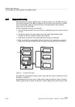
Страница 43: ...st therefore be suppressed using one of the circuits below Even with small relays interference voltages of up to 800 V occur on 24 V coils and interference voltages of several kV occur on 230 V coils when the coil is switched The use of freewheeling diodes or RC circuits prevents interference voltages and thus stray interference on conductors installed parallel to the coil conductor 9DOYHV UDNHV 5...

Страница 44: ...ross section at least 10 mm2 The distance between the signal cable and the associated equipotential bonding conductor must be as small as possible antenna effect A fine strand conductor must be used better high frequency conductivity When connecting the equipotential bonding conductors to the centralized equipotential bonding strip the power components and non power components must be combined 3RZ...

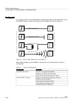
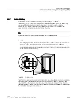
Страница 45: ...cted or incorrectly connected shield has no shielding effect As a rule For analog signal cables the shield should be connected at one end on the receiver side For digital signals the shield should be connected to the enclosure at both ends Since interference signals are frequently within the HF range 10 kHz a large area HF proof shield contact is necessary Figure 4 9 Cable shielding The shielding ...

Страница 46: ... to be interrupted the shield must be continued via the corresponding connector housing Only suitable connectors may be used for this purpose 6KLHOG WXUQHG XSVLGH GRZQ WKURXJK r DQG FRQQHFWHG WR FRQQHFWRU KRXVLQJ 5XEEHU VOHHYH Figure 4 11 Interruption of shielded cables If intermediate connectors which do not have a suitable shield connection are used the shield must be continued by fixing cable c...

Страница 47: ...the EPCglobal Class 1 Gen 1 2 and ISO IEC 18000 6B standards Supports low cost SmartLabels as well as reusable rugged data media High reading speed many tags can be read simultaneously mass recording rapidly moving tags are reliably recorded Suitable for the 865 to 868 MHz UHF bands in Europe and the 902 to 928 MHz UHF band in North America Up to 4 antennas can be connected and configured in opera...

Страница 48: ...RF660R reader 5 1 Description RF600 5 2 System Manual 09 2005 Edition J31069 D0171 U001 A0 7618 5 1 1 Ordering data Description Machine Readable Product Code SIMATIC RF660R ...

Страница 49: ...ign of the RF660R reader Item No Description 1 Status LED 2 Industrial Ethernet RJ45 connector 3 RS 422 interface 8 pin M12 connector 4 RS 232 interface 5 pin M12 connector 5 Digital I O 8 pin M12 connector 6 Power 24 V DC 4 pin M12 connector Description 4 antenna connections ANT 1 to ANT 4 RTNC connector ...

Страница 50: ...01 A0 7618 5 1 3 Status displays Status displays LEDs Color Meaning Power on Green Power supply ON also lit for undervoltage overvoltage Tag Detect Yellow LED is lit as soon as any tag is in the field System Error Red Reader is not active Rebooting is necessary operating voltage Off On ...

Страница 51: ...ng 1 2 3 4 5 6 7 8 GND not connected RS422_RX_PLUS RS422_RX_MINUS RS422_TX_MINUS RS422_TX_PLUS GND housing RS 232 connector Pin Meaning 1 2 3 4 5 6 7 8 GND RS232_TX GND RS232_RX GND not connected not connected not connected Industrial Ethernet Pin Meaning 1 2 3 4 5 6 7 8 Transmit Data Transmit Data Receive Data Terminated Terminated Receive Data Terminated Terminated ...

Страница 52: ... J31069 D0171 U001 A0 7618 5 1 5 Pin assignment and connections of the digital I O interface Pin assignment Digital I O socket Pin Meaning 1 2 3 4 5 6 7 8 Input USER_IN 0 Input USER_IN 1 Input USER_IN 2 GND IN Output USER_OUT 0 Output USER_OUT 1 Output USER_OUT 2 Housing ...

Страница 53: ...H 9HU EUDXFKHU 9HU EUDXFKHU 9HU EUDXFKHU Figure 5 2 Connections for digital I O Output USER_OUT 0 1 2 1 These are high side switches that switch Vcc 24V at low resistance active high 2 Each output is rated for 0 5 A current and is electronically protected 3 The 0 V rail is Pin 4 GND 4 Each pin of the 8 pin connector can carry a load of up to 2 A this means that three digital outputs can be operate...

Страница 54: ...ader 5 1 Description RF600 5 8 System Manual 09 2005 Edition J31069 D0171 U001 A0 7618 5 1 6 Power supply Pin assignment of the power connections Power connector Pin Meaning 1 2 3 4 Ground 0V 24 V 24 V Ground 0V ...

Страница 55: ...ables or signal cables are safely discharged to earth Required tool for protective earth terminal TORX T20 screwdriver Ground connection protective earth terminal The protective earth terminal M4 threads 1 on the device large surface large area contact has to be connected with the protective earth conductor of the plant or the cabinet in which the reader is to be installed The minimum conductor cr...

Страница 56: ...ing Concrete 8 mm diameter 60 mm depth Rawlplug 8 mm diameter 50 mm length Screws 4 mm diameter 50 mm length Plasterboard min 13 mm thick 14 mm diameter Tilting rawlplug 4 mm diameter 50 mm length Metal min 2 mm thick 5 mm diameter M4 metal screws 4 mm diameter 15 mm length Warning Ensure that the wall or ceiling can hold four times the total weight of the device 5 4 Configuration integration 5 4 ...

Страница 57: ... 5 GHYLFH GDWD PDQDJHPHQW 6 0 7 6 WKURXJK RSWLRQDO LQWHUIDFH PRGXOH 3 LQWHUIDFLQJ IRU FRQILJXUDWLRQ DQG GLDJQRVWLFV QWHQQD 6 0 7 5 5XJJHG KRXVLQJ ZLWK KLJK 3 GHJUHH RI SURWHFWLRQ 8S WR DQWHQQDV RQ RQH 5 5 UHDGHU 3URFHVV FRQWURO GLJLWDO LQSXW 9 GLJLWDO RXWSXW 9 3RZHU VXSSO 5HDGHUV 6 0 7 5 5 8S WR P IRU HDFK DQWHQQD b9 9 56b 56b WKHUQHW 7 3 3 Figure 5 3 Configuration overview of the RF660R reader No...

Страница 58: ...cation XML protocol Transmission rates 115200 bps Start bits 1 Data bits 8 Parity Odd Stop bits 1 RS422 communication 3964R protocol Transmission rate 9600 19200 38400 57600 115200 bps autobauding Start bits 1 Data bits 8 Parity Odd Stop bits 1 Ethernet communication The Ethernet interface offers automatic selection between 10BaseT and 100BaseTX Shielded Twisted Pair patch cables with standard RJ4...

Страница 59: ...RF660R reader 5 5 Maintenance and service RF600 System Manual 09 2005 Edition J31069 D0171 U001 A0 7618 5 13 5 5 Maintenance and service ...

Страница 60: ...20 x 145 x 100 without connections Material Aluminum Frequencies European frequency range 865 868 MHz 10 subchannels LBT at 2 W ERP 15 subchannels LBT at 0 1 W ERP North American frequency range 902 928 MHz 50 channels frequency hopping Frequency accuracy max 10ppm Channel spacing Channel spacing FHSS 200 kHz FHSS 500 kHz Modulation methods DSB Modulation SSB Modulation Encoding Manchester or Puls...

Страница 61: ... ISO 18000 6B Reading incl TCP IP tag to reader link frequency 320 kbps at 3 m 80 kbps at 5 m 40 kbps at 5 m 160 kbps at 3 m 40 kbps at 5 m Reading incl TCP IP reader to tag mean data transfer rate 128 kbps at 3 m 53 3 kbps at 5 m 26 7 kbps at 5 m 40 kbps at 5 m Time required to program an individual EPC tag with a 96 bit ID using WRITE min 110 to 130 ms Up to 60 ms Time required to program an ind...

Страница 62: ...rage 40 C to 85 C Electromagnetic compatibility Status displays on the device Power On Green LED Tag Presence Yellow LED Error Red LED Interfaces Antenna connections 4x RTNC connector Output values 4 W with 4 dB cable attenuation and 6 dB antenna amplification Minimum output voltage 100 mW Max independently operating antenna channels 2 Ethernet 10BaseT or 100BaseTx 1x RJ45 connection according to ...

Страница 63: ... 7 Dimension drawings RF600 System Manual 09 2005 Edition J31069 D0171 U001 A0 7618 5 17 5 7 Dimension drawings 5 7 1 Dimension drawings UGXQJVDQVFKOXVV OOH 0D DQJDEHQ LQ PP Figure 5 4 Dimension drawing of the reader ...

Страница 64: ...t any interference received including interference that may cause undesired operation Caution Any changes or modifications not expressly approved by the party responsible for compliance could void the user s authority to operate the equipment 5 8 2 Compliance distance for RF Exposure The Transmitter is within the Health Canada and FCC limits for General Population Uncontrolled Exposure to electrom...

Страница 65: ...RF660R reader 5 8 Certificates and approvals RF600 System Manual 09 2005 Edition J31069 D0171 U001 A0 7618 5 19 ...

Страница 66: ......

Страница 67: ...e antenna is available in two different frequency ranges that have been specified for the regions of Europe and USA Frequency range The antenna for Europe operate in the frequency range of 865 to 868 MHz The antenna for the USA operate in the frequency range of 902 to 928 MHz Design of the RF660A The antenna is installed in a rectangular plastic housing PP PP Front view PP Side view RTNC connectio...

Страница 68: ...ing characteristic The characteristic curve is shown for horizontal alignment and for a frequency of 865 MHz The radiating receiving angle of the antenna is defined by the angle between the two 3dB points 3KL r G G G HZLQQ LQ G LQNHO LQ UDG Figure 6 1 Effective range of radiation at 865 MHz horizontal alignment ...

Страница 69: ...nas 6 1 RF660A antenna RF600 System Manual 09 2005 Edition J31069 D0171 U001 A0 7618 6 3 Ordering data Description Machine Readable Product Code RF660A for Europe 6GT2 810 0AA00 RF660A for USA 6GT2 810 0AA01 ...

Страница 70: ...d minimum and maximum spacings for mounting antennas A minimum spacing of 50 cm is necessary between the antenna and liquids or metals The distance between the antenna and the floor should also be at least 50 cm PLQ FP PLQ FP ุ 0HWDO UDFN LTXLG Figure 6 2 Distance to the environment The distance between two antennas mounted alongside each other or one above the other should be at least 20 to 50 cm...

Страница 71: ...U001 A0 7618 6 5 FP Figure 6 3 Antennas mounted adjacently horizontally or vertically For a portal configuration the distance between two antennas that are connected to the same reader is up to 3 5 m in Europe or 4 m in the USA XURSH PD P 86 PD P Figure 6 4 Portal configuration ...

Страница 72: ...systems are available for fixing the antenna Rigid fixing with VESA 100 x 100 Flexible fixing with VESA 75 x 75 Fixing with VESA 100 x 100 Rigid fixing with an antenna adapter plate is suitable for Wall mounting on solid foundations Mast mounting Antenna with antenna adapter plate Description Keyhole for wall mounting 4 x Elongated hole for mast mounting 4 x Standardized VESA fixing holes 4 x ...

Страница 73: ...Antennas 6 1 RF660A antenna RF600 System Manual 09 2005 Edition J31069 D0171 U001 A0 7618 6 7 Antenna with antenna adapter plate Description Dimensions for fixing holes All dimensions in mm ...

Страница 74: ... J31069 D0171 U001 A0 7618 Fixing with VESA 75 x 75 Flexible mounting is possible using the VESA 75 x 75 mounting set VESA 75 x 75 mounting set Description Swivel range of wall mounting Distances for wall mounting VESA adapter plate from VESA 75 x 75 to VESA 100 x 100 ...

Страница 75: ... 10 m and 20 m with the optimal impedance are available for connection The cable between antenna and reader can be up to 20 m in length Notice Only use original Siemens antenna cables Figure 6 5 Rear of antenna with RTNC connection When less than four antennas are used we recommend that the antennas are connected to the reader as follows Number of antennas Connections on the reader 2 antennas ANT ...

Страница 76: ...8 RF660A antenna 902 928 Frequency range 865 868 MHz 902 928 MHz Impedance 50 Ohm nominal 50 Ohm nominal Antenna amplification 5 7 dBil 6 dBic VSWR 2 1 max 2 1 max Polarization RH circular RH circular Radiating receiving angle 55 60 60 75 Connector RTNC RTNC Degree of protection IP 65 IP 65 Permissible ambient temperature 25 C to 75 C 25 C to 75 C ...

Страница 77: ...integral chip Commands received from reader Responses are transmitted to the reader antenna by modulating the reflected radio waves backscatter technique 5HIOHFWHG DQG PRGXODWHG ZDYH IURP WDJ WUDQVSRQGHU 5 5 5HD QWHQQD QWHQQD 0LFURFKLS ZLWK LQWHJUDWHG 0HPRU OHFWURPDJQHWLF ZDYHV IURP UHDGHU DQWHQQD 7UDQVSRQGHU QWHQQD Figure 7 1 Mode of operation of transponders The transmission ranges achieved vary...

Страница 78: ...bal EPC Global groups tags into the following classes and generations EPC class Definition Programming Supported by RF 600 Class 0 Passive read only tags Programming by the manufacturer No Class 1 Passive single write tags Programming by the customer cannot be reprogrammed Yes Class 2 Passive rewritable tags Class 3 Semi passive tags Class 4 Active tags Freely programmable No Characteristic Genera...

Страница 79: ...the air interface protocol There are two versions ISO 18000 6 Type A and ISO 18000 6 Type B Type B Type A Frequency range 860 to 960 MHz 860 to 960 MHz Transmission procedure Bi phase modulation and Manchester encoding Pulse Interval Encoding PIE Anti collision techniques Adaptive binary tree technique ALOHA technique Protocol Reader talks first Reader talks first Supported by RF 600 Yes No ...

Страница 80: ...red on a transponder tag and scanned by the reader Different EPC versions exist from 64 to 204 bits The structure of a 96 bit EPC is shown below HDGHU 3 0DQDJHU 2EMHFW ODVV 6HULDO 1XPEHU ELWV 3 9HUVLRQ ELWV ELWV ELWV HUVWHOOHU 3URGXNW HLQGHXWLJH 6HULHQQXPPHU Header This identifies the EPC identification number that follows with regard to length type structure and version of the EPC EPC manager num...

Страница 81: ...618 8 1 Accessories 8 Accessories Order No Antenna cable Up to 20 m Cable RS 422 Up to 50 m RS 232 Up to 10 m Ethernet Up to 20 m Mounting set Yes 2 different types Further accessories Documentation on CD ROM Wide range power supply unit for SIMATIC RF systems ...

Страница 82: ... range power supply unit for RF systems 1 DC output 1 2 DC output 2 3 Mains connection Features Wide range input for use worldwide Dimensions without mains cable 175 x 85 x 35 mm Dimensions including mains cable 250 x 85 x 35 mm CE compatible Mechanically and electrically rugged design Secondary side 24V DC 3A Short circuit and no load stability Suitable for frame mounting 3 designs for use in the...

Страница 83: ...n efficient cost saving solution for many different mid range power supply tasks The primary switched power supply is designed for use on single phase AC systems The two DC outputs sockets are connected in parallel and protected by a built in current limiting circuit against overload and short circuits The device is vacuum cast prepared for applications of Safety Class 2 and satisfies the low volt...

Страница 84: ...must also be taken into account Failure to observe this requirement shall constitute a revocation of the CE approval and manufacturer s warranty For installation of the power supply compliance with the DIN VDE requirements or the country specific regulations is essential The field of application of the power supply is limited to Information technology in electrical office equipment within the scop...

Страница 85: ... D0171 U001 A0 7618 8 5 8 1 5 Connecting There are three different country specific mains cables for the EU UK and US The appropriate mains cable must be connected to the primary input of the power supply The wide range power supply unit has total insulation Safety Class 2 Can be mounted using four fixing holes ...

Страница 86: ...ally max 96 C Storage temperature 40 C to 85 C Self heating on full load max 45 K Interference immunity ESD HF fields Burst Surge HF injection Mains quality test EN 61000 4 2 4 3 up to 4 6 4 11 Air discharge 15 kV 10 V m symmetrical 2 Symmetrical 1 10 Vrms Cooling Free convection Dimensions L x W x H tbd x 85 0 x 35 0 mm Weight 720 g Housing casting UL 94 V0 Power supply class according to CSA Lev...

Страница 87: ... 70 C 0 01 K Overload behavior Pover Constant current Short circuit protection No load response Continuous no load stability Derating TA 50 C to 70 C max 2 K Connector type Flanged connector Fa Binder Order No 09 3431 90 04 4 pins Table 8 4 Output configurations Input Outputs U1 U2 ILoad I1 I2 Efficiency Remarks 110 V AC 24 V DC 0A No load stability 110 V AC 24 V DC 3A 88 220 V AC 24 V DC 0A No lo...

Страница 88: ...1 U001 A0 7618 8 1 7 Modification possibilities Output voltages Insulation strength up to 4 kVAC Heatsink DIN rail mounting 8 1 8 Pin assignment of DC outputs and mains connection DC outputs Assignment 1 Ground 0V 2 24 V DC 3 24 V DC 4 Ground 0V Mains connection Assignment 1 100 to 240 V AC 2 n c 3 100 to 240 V AC 4 n c ...

Страница 89: ...cessories 8 1 Wide range power supply unit for SIMATIC RF systems RF600 System Manual 09 2005 Edition J31069 D0171 U001 A0 7618 8 9 8 1 9 Dimension drawing s s s Units of measurement All dimensions in mm ...

Страница 90: ...Accessories 8 1 Wide range power supply unit for SIMATIC RF systems RF600 8 10 System Manual 09 2005 Edition J31069 D0171 U001 A0 7618 ...

Страница 91: ... indicative of the corresponding approval DIN ISO 9001 certificate The quality assurance system for the entire product process development production and marketing at Siemens fulfills the requirements of ISO 9001 corresponds to EN29001 1987 This has been certified by DQS the German society for the certification of quality management systems EQ Net certificate no 1323 01 Certification for the USA C...

Страница 92: ...rwriters Laboratories UL according to Canadian standard C22 2 No 60950 I T E or C22 2 No 142 IND CONT EQ Underwriters Laboratories UL according to standard UL 60950 Report E11 5352 and Canadian standard C22 2 No 60950 I T E or UL508 and C22 2 No 142 IND CONT EQ UL recognition mark Canadian Standard Association CSA per Standard C22 2 No 60950 LR 81690 or per C22 2 No 142 LR 63533 Canadian Standard ...

Страница 93: ...s likely to cause harmful interference in which case the user will be required to correct the interference at his own expense Shielded Cables Shielded cables must be used with this equipment to maintain compliance with FCC regulations Modifications Changes or modifications not expressly approved by the manufacturer could void the user s authority to operate the equipment Conditions of Operations T...

Страница 94: ...50 222 Fax 49 0 180 5050 223 Internet Visit our site on the Internet at http www siemens com automation service support You can send a support query to http www siemens de automation support request You can find the latest general information about our identification systems on the Internet at http www siemens de simatic sensors The online catalog and the online ordering system is available at htt...

Страница 95: ...our local Siemens office The addresses are found on the following pages On the Internet at http www siemens com automation partner In catalog CA 01 In Catalog FS 10 specially for factory automation sensors A 4 Training Training center We offer appropriate courses to get you started Please contact your regional Training Center or the central Training Center in D 90327 Nuremberg Telephone 49 911 895...

Страница 96: ...Appendix A 4 Training RF600 A 6 System Manual 09 2005 Edition J31069 D0171 U001 A0 7618 ...

Страница 97: ...7 Basic rules 4 20 Cable shielding 4 29 Definition 4 20 Equipotential bonding 4 28 Overview 4 19 Propagation of electromagnetic interference 4 23 Equipotential bonding 4 28 G Gate configuration Application areas 4 3 Arrangement of antenna 4 3 Generations 7 2 I Identification system Performance Features 3 3 UHF range 3 1 Influence of Interference 4 13 Liquids 4 15 Metals 4 14 Non metallic substance...

Страница 98: ...on 5 10 Design 5 3 Dimensions 5 17 Examples of mounting types 5 10 FCC information 5 18 Interfaces 5 5 5 6 5 10 Power supply 5 8 Status displays 5 4 Technical specifications 5 14 Transmission protocols 5 12 S Safety Information 2 1 Service A 4 Shielding 4 29 Status LEDS of the RF660R reader 5 4 Support A 4 System overview SIMATIC RF600 3 1 System requirements RF600 3 3 T Technical specifications R...

Отзывы: