


Detailed descriptions
16.5 BIOS Setup
SIMATIC Rack PC 840 V2
Operating Instructions, Edition 05/2006, A5E00248055-04
16-23
16.5.3
BIOS Setup menus
The various menus and submenus are listed on the next pages. You can obtain information
on the selected SETUP item from the "item-specific help" part of the respective menu.
3KRHQL[%,266HWXS8WLOLW\
,WHP6HOS
(6&
([LW
6HOHFW,WHP
6HOHFW0HQX
6HOHFW
&KDQJH9DOXHV
6XE0HQX
)
)
6HWXS'HIDXOWV
6DYHDQG([LW
(QWHU
+HOS
)
6HFXULW\
%RRW
9HUVLRQ
([LW
0DLQ
$GYDQFHG
3RZHU
6\VWHP7LPH
6\VWHP'DWH
>@
>
@
'LVNHWWH$
3ULPDU\0DVWHU
%RRW2SWLRQV
.H\ERDUG)HDWXUHV
+DUGZDUH2SWLRQV
6\VWHP0HPRU\
.%
([WHQGHG0HPRU\
.%
3ULPDU\6ODYH
0HPRU\&DFKH
>:ULWH%DFN@
6HFRQGDU\0DVWHU
6HFRQGDU\6ODYH
>1RQH@
>&'520@
>1RQH@
>0%@
>0%ಯ@
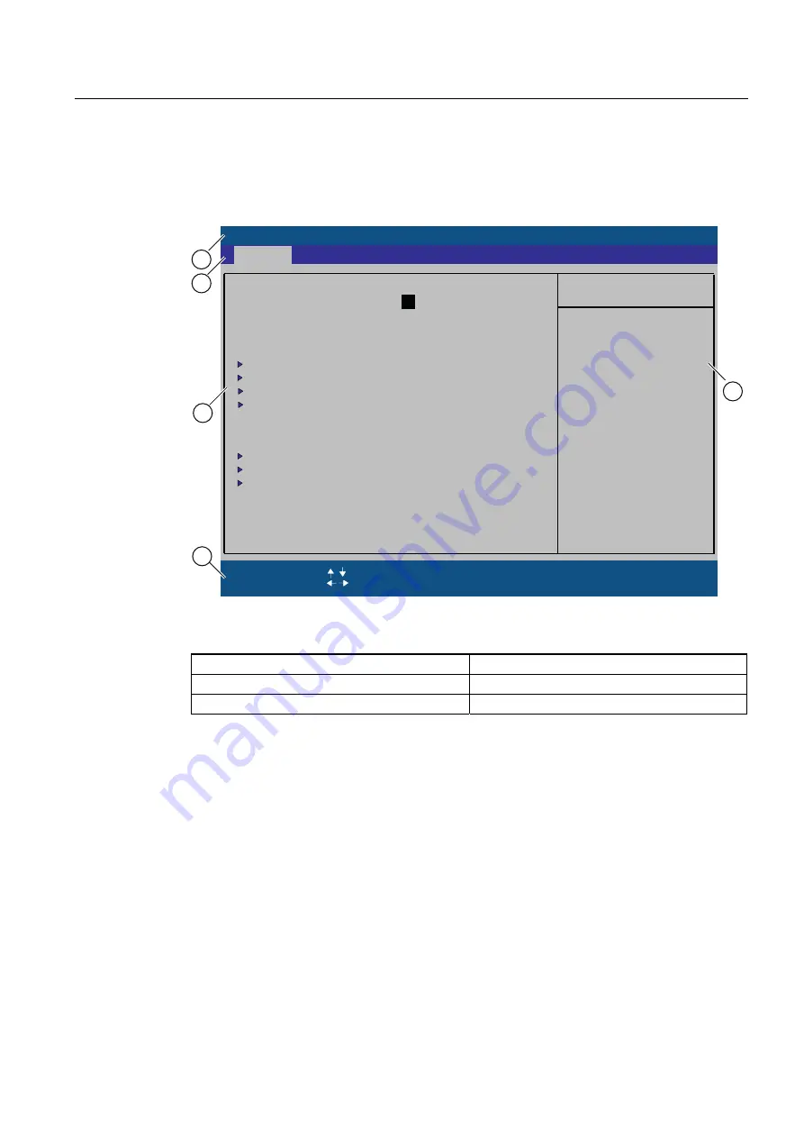
Figure 16-4 BIOS-SETUP Menu (example)
(1) Header
(4) Help view
(2) Menu line
(5) Input line
(3) Selectable submenu
Menu layout
The screen is divided into four sections. In the top part (2), you can select the menu forms
[Main], [Advanced], [Security], [Power], [Boot Sequence], [Version], [Exit]. In the left of the
center section (3) you can select various settings or submenus. Brief help texts appear on
the right (4) for the currently selected menu entry. The bottom section contains information
for operator input.
The figures below represent examples of specific device configurations. The screen content
changes based on the supplied equipment configuration.
Yellow stars to the left of the interface designation (for example, Internal COM 1) indicate a
resource conflict between the interfaces managed by the BIOS. In this case you should
select the default settings (F9) or eliminate the conflict.
You can move between the menu forms using the cursor keys [←] left and [→] right.


