


Application planning
3.5 Mounting positions and fastening
SIMATIC PC Panel PC 677/877, Control Unit
Operating Instructions, Edition 04/2005, A5E00407724-01
3-5
•
Ensure there is enough free space in the switchgear cabinet to allow the sheet metal
cover to be removed. You will otherwise have to remove the device from the switchgear
cabinet or boom when replacing memory or the battery.
•
Also provide enough free space to add on to the device.
•
Equip the switchgear cabinet with struts for stabilizing the installation cut-out. Install struts
where necessary.
•
Avoid extreme environmental operating conditions. Protect your device against dust,
moisture and heat.
•
Install the device in such a way that it poses no danger, e.g. by falling over.
•
During assembly, please comply with the approved installation positions.
Notice
If the device is installed in an unapproved position, the licenses expire in accordance with
UL 508 and EN 60950!
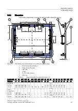
For additional information, refer to the dimension diagrams in the appendix.
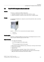
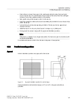
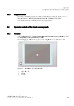
3.5.2
Permitted mounting positions
Approval
Certain installation positions are approved for the device.
Figure 3-3
Approved installation positions for central design
Vertical installation and deviations b20° and -20° in the given directions is
permitted.


