background image

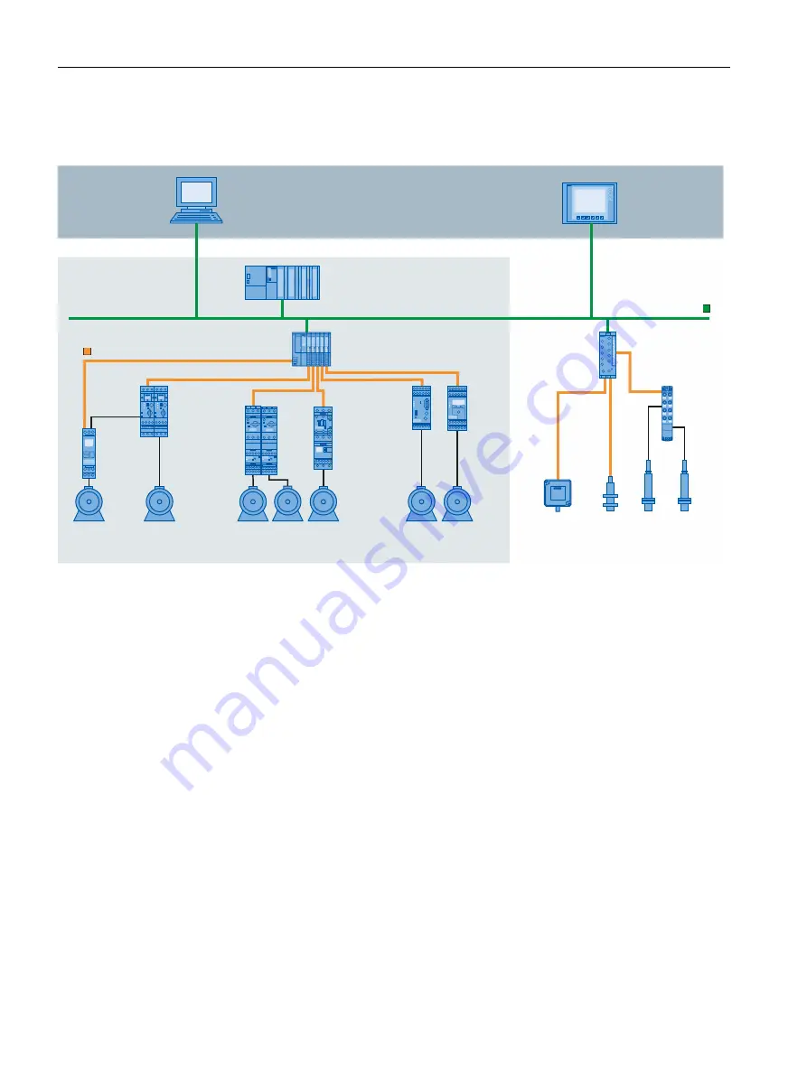
Example plant with IO-Link

The figure below shows an example of plant architecture with IO-Link.

7JTVBMJ[BUJPO

4*."5*$).*8JO$$

'JFMEJOTUBMMBUJPO

4*."5*$

&5FDP1/.-

XJUI*0-JOLNBTUFS

&5"-

*0-JOL*0

NPEVMF

4UBOEBSE

TFOTPST

3'*%TZTUFN

3'

3'*%TZTUFN

3'

4*3*64

SFMBZ

34

34

4*3*64

PWFSMPBE

SFMBZ3#

4*3*64DPOUBDUPS

35XJUI4*3*64

SFMBZ33

4*3*64MPBE

GFFEFST3"

XJUIGVODUJPO

NPEVMFT3"

4*3*64DPNQBDU

TUBSUFST3"

4*3*64

SFMBZ

6(

*0-JOL

&541

XJUI*0-JOLNBTUFS

44

BVUPNBUJPOTZTUFN

*OTUBMMBUJPOJODPOUSPMDBCJOFU

41$5

"DUVBUPST

130'*/&5

Figure 2-1  Plant architecture with IO-Link

The IO-Link master establishes the connection between the IO-Link devices and the
automation system. If the IO-Link master is a component of the I/O system, it is installed
either in the control cabinet or directly in the field as remote I/O in degree of protection
IP65/67. The IO-Link master communicates by means of various fieldbuses or product-specific
backplane buses. An IO-Link master can have multiple IO-Link ports (channels). An IO-Link
device can be connected (point-to-point communication) to each port.

Engineering

The IO-Link system is engineered parallel to the overall automation system and can be
embedded in it and intermeshed with it.

2.3 

IO-Link interface

Introduction

The IO-Link is a serial, bidirectional point-to-point connection for signal transmission and
power distribution under any network, fieldbus or backplane bus.

10

IO-Link system

Function Manual, 07/2022, A5E31637677-AC

System overview

2.3 IO-Link interface

Содержание SIMATIC IO-Link system

Страница 1: ...Guide 1 System overview 2 Integration into the automation system 3 SIMATIC IO Link system Function Manual 07 2022 A5E31637677 AC ...

Страница 2: ... by personnel qualified for the specific task in accordance with the relevant documentation in particular its warning notices and safety instructions Qual ified personnel are those who based on their training and experience are capable of identifying risks and avoiding potential hazards when working with these products systems Proper use of Siemens products Note the following WARNING Siemens produ...

Страница 3: ... IO Link systems at Siemens The product documentation is based on this documentation Conventions In this documentation STEP 7 is used as a synonym for all versions of the configuration and programming software STEP 7 TIA Portal Please also observe notes marked as follows NOTE A note contains important information on the product described in the documentation on the handling of the product or on th...

Страница 4: ...ilable and that the latest product versions are used Use of product versions that are no longer supported and failure to apply the latest updates may increase customers exposure to cyber threats To stay informed about product updates subscribe to the Siemens Industrial Security RSS Feed visit https www siemens com cert Siemens Industry Online Support You can find current information on the followi...

Страница 5: ...You can find catalogs for all automation and drive products on the Internet https mall industry siemens com IO Link system Function Manual 07 2022 A5E31637677 AC 5 Preface ...

Страница 6: ...1 0 and V1 1 17 3 Integration into the automation system 18 3 1 Configuration of the IO Link system 18 3 1 1 Configuration with S7 PCT 20 3 1 2 Configuration without S7 PCT 22 3 1 3 Overview of configuration options 24 3 2 Data access of the automation system and the HMI device 26 3 3 Changing and saving device parameters during plant operation 27 3 4 Replacing a master or device during operation ...

Страница 7: ... Device I O modules Device industrial switchgear Device RFID systems RFID radio frequency identification Port Configuration Tool S7 PCT https support industry siemens com cs ww en view 32469496 IO Link library https support industry siemens com cs ww en view 82981502 with the blocks LIOLink_MasterIO_LINK_MASTER and LIOLink_Device Overview of the topic IO Link http www siemens com io link Additiona...

Страница 8: ...e following system components IO Link master IO Link device Unshielded 3 wire or 5 wire standard cable Engineering tool for configuring and assigning parameters of IO Link 2 1 Advantages of IO Link The IO Link system offers significant advantages as digital interface when connecting sensors actuators Open standard in accordance with IEC 61131 9 Devices can be integrated in the same way in all conv...

Страница 9: ...of the machine Automatic reassignment of parameters when devices are replaced during operation Minimization of downtimes Device replacement by untrained personnel without additional aids Avoidance of incorrect settings Integrated device identification Identification of the installed devices Ensure quality of result in production and manufacturing when replacing the device 2 2 Overview of IO Link s...

Страница 10: ...ystem If the IO Link master is a component of the I O system it is installed either in the control cabinet or directly in the field as remote I O in degree of protection IP65 67 The IO Link master communicates by means of various fieldbuses or product specific backplane buses An IO Link master can have multiple IO Link ports channels An IO Link device can be connected point to point communication ...

Страница 11: ...n 4 Switching and communication cable C Q In addition to IO Link communication these three pins also implement the power supply of the device Detailed information about the power supply can be found in the documentation of the utilized IO Link master NESV 6WDQGDUG HILQLWLRQ 6LJQDO 3LQ QRW GHILQHG 6ZLWFKLQJ VLJQDO 4 6 2 FRGHG VZLWFKLQJ VLJQDO 2 LQN 6WDQGDUG 2 86 0 4 86 0 4 6 2 2 LQN 6 2 9 9 Figure ...

Страница 12: ...s that have an increased power requirement In this case an additional galvanically isolated supply voltage is made available by pins 2 and 5 A 5 wire standard cable is required to use this additional supply voltage 0 86 0 4 Figure 2 4 Pin assignment Port Class B Connecting cables The devices are connected to the master with unshielded 3 wire or 5 wire standard cables with a maximum length of 20 m ...

Страница 13: ...me of the device is stored in the device description file IODD of the device Page 15 This value indicates in which time intervals the master may address the device The value has a big influence on the response time The master also has an internal processing time that is factored into the calculation of the response time Devices with different minimum cycle time can be configured on a master The re...

Страница 14: ...he request of the IO Link master Device data can be written to the device and also read from the device Events When an event occurs the device signals to the master that an event is present The master then reads the event Events can be error messages for example short circuit and warning maintenance data for example dirt overheating Error messages are transferred from the device to the CPU or the ...

Страница 15: ...cially suited for measurement sensors In other words measured values are transmitted in addition to switching points In addition the switchgear for example contactors support the LVSG Low Voltage Switchgear profile defined in IEC 61915 2 2 6 IODD and Port Configuration Tool S7 PCT Device description IODD An electronic device description the IODD file IO Device Description is available for each dev...

Страница 16: ...to the ports of the master Address assignment of ports within the address area of the master Assigning parameters for the IO Link device Diagnostics can also be carried out on the connected devices This means the IO Link configuration tool supports the transparent representation of the IO Link system down to field level Siemens provides S7 PCT for engineering of the IO Link system S7 PCT with IODD...

Страница 17: ...Data transmission rate 230 4 kBaud is mandatory for the IO Link master Combination of IO Link devices Note the following when combining IO Link devices Only IO Link devices that comply with V1 0 can be operated on the IO Link master to V1 0 IO Link devices that comply with V1 0 and V1 1 can be operated on the IO Link master to V1 1 Data backup and a data transmission rate of 230 4 kBaud of the IO ...

Страница 18: ...tem is represented by the IO Link master in the configuration of the automation system or the fieldbus and integrated with STEP 7 or a GSD file The IO Link master itself can be a field bus node e g ET 200eco PN IO Link master or a part of the modular IO system that is connected to the field bus e g ET 200SP IO Link master In both cases the number of ports the address range and the module propertie...

Страница 19: ...t you also want to work with the S7 PCT configuration tool NOTE IO data length To ensure smooth operation select an IO data length during configuration of the IO Link master that corresponds at least to the IO data length of all connected IO Link devices If necessary the IO Link master offers the option of configuring the IO data length for each individual port In this case the IO data length must...

Страница 20: ...re also making the settings of the IO Link master ports with S7 PCT See Figure 3 5 Page 22 These settings include Specification of the address range for each port Behavior when replacing an IO Link device Setting the identification data for checking the connected IO Link device type Start S7 PCT from HW Config in STEP 7 S7 PCT shows you all Siemens IO Link masters you have configured in your autom...

Страница 21: ...s ranges of the ports can be changed The IO Link master transfers the process values that it receives from the IO Link device in these address ranges and makes the process values available to the higher level automation system To set the address range select the Addresses tab Setting device parameters Specific parameter settings are required to adjust the device to the respective application task ...

Страница 22: ...rinting the configuration and the parameters It is not possible to change parameters in online mode 3 1 2 Configuration without S7 PCT Introduction The following sections describe how you configure your IO Link master without the S7 Port Configuration Tool S7 PCT Your options for configuration of the IO Link system without S7 PCT are limited You can configure the port of the IO Link master using S...

Страница 23: ...l input DQ The port is operating as a standard digital output Disabled The port is disabled Input Data Length Process data length of the input data Output Data Length Process data length of the output data Vendor ID ID number of the device manufacturer You can find the Vendor ID on the Internet https support industry siemens com cs ww en view 109748852 Device ID ID number of the device You can fin...

Страница 24: ...vides an overview of the available options for configuration with and without S7 PCT Configuration without S7 PCT Requirement Configuration with S7 PCT IO Link Autostart IO Link Manual Use of the IO Link device description IODD Yes No No Setting the length of input and output data per port Automatic Manual Manual Assignment of the Vendor ID and Device ID Automatic Manual see FAQ https support indu...

Страница 25: ...ons module IO Link Master CM 8xIO Link 6ES7547 1JF00 0A B0 V1 0 x x ET 200SP V1 0 0 x Communications module IO Link Master CM 4xIO Link 6ES7137 6BD00 0 BA0 V2 2 0 x x ET 200AL V1 0 0 x Communications module CM 4xIO Link 4xM12 6ES7147 5JD00 0B A0 V1 1 0 x x ET 200eco PN IO Link master 4 IO L 8 DI 4 DO DC 24V 1 3A 8 M12 6ES7148 6JA00 0A B0 V6 1 0 x IO Link master 4 IO L 4 M12 6ES7148 6JD00 0 AB0 V1 ...

Страница 26: ...rs of the device or master during operation Function blocks LIOLink_Master and LIOLink_Device The programming of the CPU user program is another task in addition to the configuration and parameterization of the IO Link system and its integration into the overall automation system For acyclic data exchange you can use the function blocks LIOLink_Master and LIOLink_Device for controllers of the S7 3...

Страница 27: ...through operation on the device local operating unit on the device Saving device parameters backup You can also automatically save the parameters set in the device during commissioning or changed during operation of the plant in the IO Link master This data backup takes place depending on the set behavior of the IO Link master ports You can set the following data backup levels None No data backup ...

Страница 28: ...U user program IO Link device parameters can be changed successively by the user program A backup is only triggered by a system command The system command must be triggered by the user program after the parameter changes You can implement the parameter changes and the system command for triggering the backup with function blocks of the CPU Using the HMI You proceed as with triggering by the user p...

Страница 29: ...ensors When you are using sensors that must be adapted to specific rated conditions on site field calibration you must repeat this calibration after replacing the device The backup does not include the data of the field calibration After repeating the field calibra tion the new device works just like the replaced device Replacing a master Replacing a master during operation is a rather rare scenar...

Отзывы: