background image


Compact Operating Instructions 


1.6 Affixing Labeling Strips for Function Keys and Softkeys 

SIMATIC HMI IPC477C / HMI IPC477C PRO 
Compact Operating Instructions, 10/2010, A5E02368072-02 

9


Preparing the labeling strips 

1.


Label the DIN A4 film with a laser printer, for example using the printing templates 

provided on the Documentation and Drivers CD. 

2.


Cut the labeling strips along the pre-printed lines. 


Note 
Do not insert handwritten labeling strips until the ink has dried.  


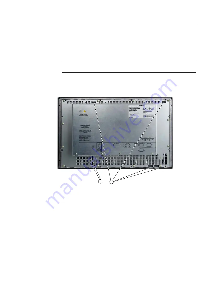
Affixing the labeling strips 

Insert the labeling strips into the slots provided on the rear of the control unit. 


Insert strips, vertical key rows 


Insert strips, horizontal key rows 

Figure 1-1 

12" touch screen device: Device rear with labeling strips 

Содержание SIMATIC HMI IPC477C PRO

Страница 1: ... SIMATIC HMI IPC477C HMI IPC477C PRO ___________________ SIMATIC Industrial PC SIMATIC HMI IPC477C HMI IPC477C PRO Compact Operating Instructions 10 2010 A5E02368072 02 Compact Operating Instructions 1 ...

Страница 2: ...the relevant documentation for the specific task in particular its warning notices and safety instructions Qualified personnel are those who based on their training and experience are capable of identifying risks and avoiding potential hazards when working with these products systems Proper use of Siemens products Note the following WARNING Siemens products may only be used for the applications de...

Страница 3: ...ting 17 1 8 1 Connection elements and operator controls 17 1 8 2 Connecting the 24 VDC power supply 19 1 8 3 Connecting the PE conductor 21 1 9 Commissioning 22 1 9 1 Commissioning Information 22 1 9 2 Basic commissioning initial startup 23 1 9 3 Setting up the language selection in Windows Embedded Standard 2009 24 1 9 4 Language selection in Windows Embedded Standard 7 25 1 9 5 Setting the panel...

Страница 4: ...Table of contents SIMATIC HMI IPC477C HMI IPC477C PRO 4 Compact Operating Instructions 10 2010 A5E02368072 02 ...

Страница 5: ...he correct use of the device has to be verified with a function test on the system This test can detect programming configuration and wiring errors The test results have to be documented and if necessary entered into the relevant documents that verify safety 1 2 Unpacking and checking the delivery 1 Please check the packaging material for transport damage upon delivery 2 If any transport damage is...

Страница 6: ...r put into operation 8 Note the identification information see chapter Identification data of the device Notes on display A small number of faults in the display is unavoidable Bad pixels Permissible number Permanently bright and permanently dark pixels 12 Permanently bright green pixels 5 1 3 Components of the Product Scope of delivery for SIMATIC HMI IPC477C Numbe r Name Description 1 SIMATIC HM...

Страница 7: ... arm 4 Screws Screws for mounting the basic adapter to an adapter 1 DC power plug Only supply variant with 24 V DC power supply 1 4 Device identification data Enter the identification data of the device into the table Serial number on the type plate S VP Order no of the device 6AV7 884 SIMATIC HMI IPC477C 6AV7 883 SIMATIC HMI IPC477 PRO For the versions with Windows Embedded Standard XP Profession...

Страница 8: ...S7648 2AH60 0AH0 Touch pen 6AV7672 1JB00 0AA0 Note Replace Compact Flash cards only with cards of the same product versions Only SIMATIC PC Compact Flash cards with product version number 02 ES 02 or higher can be used for this device 1 6 Affixing Labeling Strips for Function Keys and Softkeys Note The following table applies only to devices with a key panel The control unit has two horizontal and...

Страница 9: ...r for example using the printing templates provided on the Documentation and Drivers CD 2 Cut the labeling strips along the pre printed lines Note Do not insert handwritten labeling strips until the ink has dried Affixing the labeling strips Insert the labeling strips into the slots provided on the rear of the control unit Insert strips vertical key rows Insert strips horizontal key rows Figure 1 ...

Страница 10: ...ps for Function Keys and Softkeys SIMATIC HMI IPC477C HMI IPC477C PRO 10 Compact Operating Instructions 10 2010 A5E02368072 02 Insert strips vertical key rows Insert strips horizontal key rows Figure 1 2 15 touch screen device Device rear with labeling strips ...

Страница 11: ...ce Temperature at the device Rear Front Angle A Angle B 0 50 C1 Max 40 C 45 45 0 to 45 C 0 to 45 C 45 45 1 For RAL mounting only RAL Restricted Access Location installation of device in operating facilities with restricted access for example a locked control cabinet Mechanical environmental conditions Vibration Operation tested in accordance with DIN IEC 60068 2 6 10 to 58 Hz 0 075 mm 58 to 200 Hz...

Страница 12: ...tion shows the dimensions for the mounting cut out PP 6 6 6 6 6 6 6 1 Drill hole for screw attachment 4 Clamp 2 Pressure points for clamp 5 RZ 120 in the seal area 3 Setscrews 6 Seal area Figure 1 3 Drill holes for the screws and pressure points for the clamp screws Note Mounting dimensions can be read from the dimension overview or they can be transferred to the cabinet from the mounting template...

Страница 13: ...m 2 Cut outs for the shafts of the insert strips are only necessary for 15 key panels 3 Two clamps necessary for vertically securing clamps only for 19 touch panel fronts Preparing the mounting cut out Steps for preparing the mounting cut out 1 Select a location suitable for mounting taking into account the mounting position 2 On the basis of the dimensions check whether the required screw and pre...

Страница 14: ... for fastening the device with clamps 1 Follow the installation instructions 2 Disconnect the device from the power supply 3 Working from the front insert the device into the mounting cut out 4 Secure the control unit in the mounting cut out from behind with the clamps as shown in the mounting cut out in the dimensions Tighten the setscrews to a torque of 0 4 0 5 Nm IP65 degree of protection The I...

Страница 15: ...protection can only be guaranteed when the following requirements are met 1 The material strength at the mounting cut out must be at least 2 mm 2 The deviation from the plane of the mounting cut out in relation to the external dimensions for an installed HMI device is 0 5 mm Note Securing with screws is not possible with the 12 touch screen variant Required tool for fasting with screws 7 mm drill ...

Страница 16: ...ctions 2 Carefully drill the respective holes in the control unit at the designed location from the rear 3 Working from the front place the device onto the swivel arm 4 Secure the control unit by inserting suitable screws through the holes and attaching nuts Control cabinet installation Steps for fastening the device with screws 1 Follow the installation instructions 2 Drill suitable holes at the ...

Страница 17: ... Power supply connection DVI DVI I socket USB 4 USB 2 0 500 mA connections ETHERNET 2 RJ45 Ethernet connections for 10 100 1000 Mbps COM 1 Serial port 1 RS232 9 pin Cannon socket PROFIBUS DP MPI PROFIBUS DP MPI interface RS 485 electrically isolated 9 pin Cannon socket Figure 1 6 Variants with PROFIBUS ETHERNET 1 RJ45 Ethernet connection for 10 100 1000 Mbps PROFINET CP 1616 onboard interface thre...

Страница 18: ...e Use of USB devices Wait at least ten seconds between removal and reconnection of USB devices This also applies to control units with touch screen panels especially for touch operation When using standard USB peripherals bear in mind that their EMC immunity level is frequently designed for office applications only These devices may be used for commissioning and servicing However only industry sta...

Страница 19: ...ice needs to be connected to the PE conductor which is integrated in the cabinet NOTICE The 24 VDC power source must be adapted to the input data of the device see the technical specifications in the operating instructions NOTICE Permissible conductor cross section for the 24 VDC connecting cable 0 75 mm2 to 2 5 mm2 NOTICE If a Compact Flash card is used in the device make sure that the card is se...

Страница 20: ...conductor as described in section connecting the PE conductor Page 21 3 LQ 0 LQ The power consumption at 24 V amounts to 60 W maximum Connecting the IPC477C PRO Steps for connecting the IPC477C PRO to the 24 V DC power supply 1 Remove the ten screws from the rear panel of the housing 2 Lift up the rear panel slightly and then remove it 3 Connect the power supply using the connector included in the...

Страница 21: ...nterference signals generated by external power cables signal cables or cables to the I O modules are safely discharged to earth Procedure PE conductor connection for IPC477C Required tool TORX T20 screwdriver Steps for connecting the PE conductor 1 Connect the PE terminal M4 thread on the device to the PE conductor on the cabinet or system in which the PC will be installed The minimum conductor c...

Страница 22: ...formation Note Initial commissioning of Windows Embedded Standard System startup can take longer than usual for the initial commissioning Only a blue screen is displayed for several minutes NOTICE Windows Embedded Standard Observe EWF Information A configurable write filter Enhanced Write Filter is available in Windows Embedded Standard Observe the EWF information in the operating instructions dur...

Страница 23: ...1 Switch the device on using the On Off switch The device now performs an power on self test During the self test this message appears Press F2 to enter SETUP or ESC to display the Boot menu 2 Wait until this message is cleared then follow the instructions on the screen NOTICE The device may not be switched off at any time during the installation process Do not change the default BIOS settings oth...

Страница 24: ...tion of Windows Embedded Standard on a Compact Flash card or SSD 1 9 3 Setting up the language selection in Windows Embedded Standard 2009 Windows Embedded Standard 2009 offers the option of selecting the menu and dialog languages You can select the German and English languages Setting up the language selection Windows Embedded Standard 2009 is set up by default with English menu and dialog langua...

Страница 25: ...e steps Prerequisite The Legacy USB Support option has to be set to Enabled in the Advanced menu of the BIOS so that the device can address a USB CD ROM drive 1 Connect a USB CD ROM drive to the device 2 Insert the Restore CD DVD in the drive restart the device and when the BIOS message Press F2 to enter Setup or ESC to show Boot menu appears press the F2 key 3 Select the Boot menu and move the en...

Страница 26: ...ioning The SIMATIC PC Wizard implements the specific settings for the SIMATIC Panel PC during the initial startup of the operating system Several dialogs appear on screen during initial commissioning of the SIMATIC Panel PC NOTICE Start the PC for commissioning in an unchanged delivery state and follow the dialogs until their conclusion Procedure Device specific drivers are set during the hardware...

Страница 27: ...9 Commissioning SIMATIC HMI IPC477C HMI IPC477C PRO Compact Operating Instructions 10 2010 A5E02368072 02 27 1 9 5 2 Touch panel configuration Touch screen calibration 1 Calibrate the touch screen by clicking the wizard 2 Click Finish ...

Страница 28: ...user account 3 Use the Finish button to close the wizard The HMI device will be restarted automatically for the respective configuration 1 9 5 3 Key panel configuration 1 Follow all dialogs until the end 2 Click Finish Note On screen keyboard OSK If the enable checkbox is selected the Windows on screen keyboard is displayed for logon at every program start You can use it for example to enter the a...

Страница 29: ...n activation und deactivation Security features Lock function that prevents two function keys from being activated simultaneously This prevents incorrect operations and undefined states of the application program Note For a detailed description of the SIMATIC KeyTools refer to the help menu and the application description on the Documentation Drivers DVD Opening Keytools 1 Open Keytools with the c...

Страница 30: ...ings The UPDD Console dialog box opens Figure 1 8 Point calibration 2 Select the controller you wish to calibrate 3 Click the Calibration tab 4 Select the Number of points option with the 25 point calibration 5 Click Calibrate The calibration mask is output on the selected display 6 Quickly touch the corresponding selections one after the other The entry is confirmed by a check mark the next selec...

Страница 31: ...t on the selected display 5 Quickly touch the corresponding selections one after the other The entry is confirmed by a check mark the next selection is displayed 6 Confirm all input prompts arrows or crosses in the center until the complete screen has been calibrated Note If the screen does not respond to touching as expected check the specified controller marked in black in UPDD Console and repea...

Страница 32: ...og box opens 2 Select the corresponding controller The Extended touch option is preset for Windows 7 Note The Extended touch functionality is only available for Windows 7 Ultimate If Extended touch is selected the extended touch functions of Windows 7 will be available such as operating touch permanently which corresponds to the right mouse button function Note The EventSelector program works only...

Страница 33: ...ctivating the Screen Keyboard You can operate the device by means of a virtual screen keyboard You can use it to enter the characters directly on the touch screen or with the mouse Starting Touch Input Start the Touch Input application on the desktop The screen keyboard is displayed 1 Button for language selection German English Italian Spanish French ...

Страница 34: ...sted at SITRAIN homepage http www sitrain com Technical support You can contact technical support for all Industry Automation and Drive Technologies products by E mail support automation siemens com Internet Online support request form http www siemens com automation support request When you contact the customer support please have the following information for the technician on hand BIOS version ...

Страница 35: ...n Setup in Windows Embedded Standard 2009 24 M Mounting 14 Mounting positions 11 O On off switch Position of on off switch 19 Operating system Setting up Windows Embedded Standard 23 P Panel Wizard starting 26 PE conductor SIMATIC IPC477C 21 Power consumption SIMATIC IPC 477C 20 SIMATIC IPC 477C PRO 20 Protective conductor SIMATIC IPC477C PRO 21 R Rack mounting 14 16 S Screen keyboard calling 33 S...

Страница 36: ...Index SIMATIC HMI IPC477C HMI IPC477C PRO 36 Compact Operating Instructions 10 2010 A5E02368072 02 ...

Отзывы: