background image

Siemens Industry, Inc.
Building Technologies  Division

P/N 315-050537-3

8

CONFIGURING  THE SCALANCE X204-2 MULTIMODE OR X204-2LD SINGLE MODE ETHERNET FIBER SWITCH

This section describes how to assign an IP address to the Scalance X204-2 Multi-
mode or X204-2LD Single Mode Ethernet Fiber Switch and the methods used for
determining IP addresses to assign to the switches. It also describes how to config-
ure one of the switches as the ring master.

FIBER SWITCH

The fiber switch can be configured independently or in the network. The initial
configuration of the fiber switch must be made before connecting it to the system.
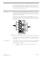
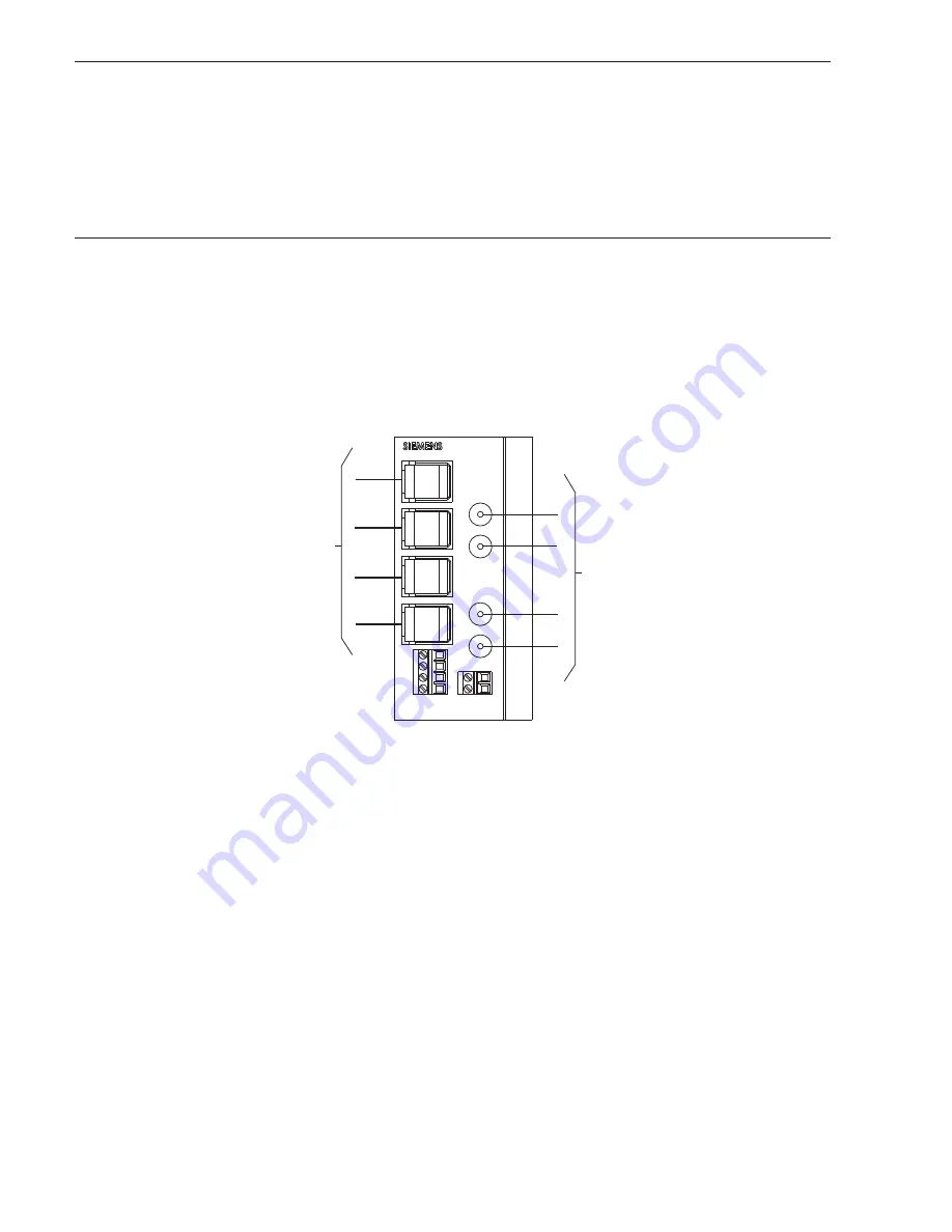
The fiber switch has four RJ-45 jacks (P1-P4) for Ethernet connections and two pair of
fiber optic connection ports (P5-P6).

Each fiber switch must be programmed with a unique IP address.  The recom-
mended range of IP addresses is from 192.168.1.201 to 192.168.1.250. In addition to
the  unique IP address, each switch is identified in the NCC by an address number
ranging from 201 to 250.

P1

P2

P3

P4

P5

P6

IN

OUT

IN

OUT

FAULT

F1

F2

L1+

M1

L2+

M2

ETHERNET

CONNECTIONS

P1 - P4

ETHERNET

CONNECTIONS

P1 - P4

FIBER
CONNECTIONS
P5 - P6

FIBER
CONNECTIONS
P5 - P6

Figure 12

Scalance X204-2 Multimode/X204-2LD Single Mode Ethernet Fiber Switch Connections

The fiber switch is powered from the battery backed up local 24V power supply. It is
monitored by the NCC. Configuration is made using a Primary Setup Tool (PST) and a
web browser.

Primary Setup Tool

The Primary Setup Tool (PST) is used to assign an IP address to an 

unconfigured

 fiber

switch. If a fiber switch is already initially configured with an IP address then the
Primary Setup tool is not needed

Install the Primary Setup Tool using the setup executable from the CD
provided.

Содержание Scalance X204-2 Multimode

Страница 1: ...the primary NCC is designated as the ring master There is no difference in installation configuration and operation of single mode or multimode fiber optic switches except the type of fiber used INSTALLATION Remove all system power before installation first battery then AC To power up connect the AC first then the battery Mounting on VNT MP The fiber switch mounts on a bracket in the lower left co...

Страница 2: ...NOT USE DO NOT USE MAXIMUM ATTENUATION 6dB MAXIMUM ATTENUATION 6dB NOTE FOR STYLE 4 CLASS B OMIT CONNECTION BETWEEN FIRST AND LAST FIBER SWITCH NOTE FOR STYLE 4 CLASS B OMIT CONNECTION BETWEEN FIRST AND LAST FIBER SWITCH Figure 5 Fiber Switch Style 7 and Style 4 Class B Wiring Connections Refer to Figure 6 for the wiring of the fiber switch in a VNT Building configuration Figure 7 shows the wiring...

Страница 3: ...T USE DO NOT USE EARTH GROUND EARTH GROUND PAIR B SUPERVISED POWER LIMITED OMIT FOR STYLE 4 PAIR A SUPERVISED POWER LIMITED NON POWER LIMITED NON POWER LIMITED SUPERVISED NON POWER LIMITED SUPERVISED NON POWER LIMITED VNT PS DO NOT USE DO NOT USE DO NOT USE DO NOT USE DO NOT USE DO NOT USE TO AIC TERMINAL 1 TO AIC TERMINAL 1 TO AIC TERMINAL 2 TO AIC TERMINAL 2 EOLR 120 OHMS 1 2W 5 P N 140 820350 A...

Страница 4: ...SE DO NOT USE DO NOT USE DO NOT USE DO NOT USE DO NOT USE KEYBOARD KEYBOARD DO NOT USE DO NOT USE SUPERVISED NON POWER LIMITED SUPERVISED NON POWER LIMITED _ L1 M1 BLK RED BLK RED 1 2 3 4 5 NCC 2F HNET CATEGORY 5 RJ45 CABLE LESS THAN 20 FT IN CONDUIT CATEGORY 5 RJ45 CABLE LESS THAN 20 FT IN CONDUIT SIEMENS BLK RED DO NOT USE DO NOT USE EARTH GROUND NON POWER LIMITED NON POWER LIMITED VNT PS VNT DO...

Страница 5: ...3060 5 033060 5 033060 or or or or or P P P P PAD 3 P N 31 AD 3 P N 31 AD 3 P N 31 AD 3 P N 31 AD 3 P N 315 5 5 5 5 099082 or 099082 or 099082 or 099082 or 099082 or P P P P PAD 4 P N 31 AD 4 P N 31 AD 4 P N 31 AD 4 P N 31 AD 4 P N 315 05021 5 05021 5 05021 5 05021 5 050217 for 7 for 7 for 7 for 7 for power power power power power Input Voltage Regulated 24VDC Input Current 265mA 24VDC Connecting ...

Страница 6: ...e It is supervised for ground fault and short and is power limited For applications where the battery charger circuit charges batteries of 7 0 A H or less or if the battery charger is dis abled this output is limited to 3 0 amps maximum For batteries between 15 A H and 7 0 A H this output is limited to 1 5 amps maximum Common Trouble Relay The UL approved power supply has a built in Form C trouble...

Страница 7: ...ELAY CONTACT SHOWN IN NORMAL STANDBY CONDITION 2A 30VDC RESISTIVE FOR POWER LIMITED SOURCE UNSUPERVISED IDC EOL SEE CONTROL UNIT INSTALLATION INSTRUCTIONS FIBER SWITCH MODULE DO NOT USE INPUT 1 INPUT 2 TB11 1 1 2 1 1 1 TB12 TB13 TB14 NAC1B NAC2B NAC1A _ _ NC COM NO NC COM 2 2 1 1 PAD 4 TO OTHER ETHERNET CONNECTIONS Figure 10 Scalance X204 2 Multimode or X204 2LD Single Mode Ethernet Fiber Switch C...

Страница 8: ... be programmed with a unique IP address The recom mended range of IP addresses is from 192 168 1 201 to 192 168 1 250 In addition to the unique IP address each switch is identified in the NCC by an address number ranging from 201 to 250 P1 P2 P3 P4 P5 P6 IN OUT IN OUT FAULT F1 F2 L1 M1 L2 M2 ETHERNET CONNECTIONS P1 P4 ETHERNET CONNECTIONS P1 P4 FIBER CONNECTIONS P5 P6 FIBER CONNECTIONS P5 P6 Figur...

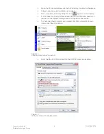
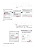
Страница 9: ...ol icon appears on the desktop A DLC Data Link Control Protokoll and Profinet IO RT Protocol need to be installed on the laptop PC being used to configure the fiber switch To check that these protocols are installed click Start Network Connec tions Local Area Connection Figure 13 Checking Local Area Connection Verify that the DLC Protokoll and Profinet IO RT Protocol are installed Figure 14 Verify...

Страница 10: ...Protocol column then click OK Figure 15 DLC Protokoll and or Profinet IO RT Protocol Installation The laptop PC being used to configure a switch needs to be on the same network as the fiber switches To do this temporarily change the IP address of the laptop PC From Local Area Connection Properties dialog window select Internet Protocol TCP IP and click Properties Choose Use the following IP addres...

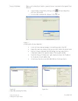
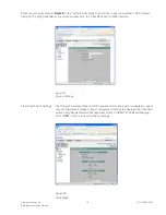
Страница 11: ...unching the Primary Setup Tool A list of all found devices displays on the left hand side of the PST Expand the device by clicking on the plus symbol before the device name Click on Ethernet Interface The PST displays the input dialog for the configuration data in the right hand pane of the program window Select the Assign IP Parameters option button and enter the IP address for the device in the ...

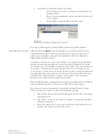
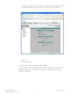
Страница 12: ...rating problem free The fiber switch operating in the redundancy manager mode monitors the connected bus over its ring ports It switches the ring ports through if there is an interruption on the connected bus In other words it restores a functioning bus over this substitute path Reconfiguration takes place within 0 3 seconds As soon as the problem has been eliminated the original topology is resto...

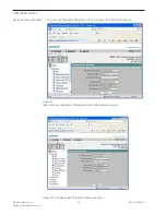
Страница 13: ...tatus of Fiber Optic Switch Figure 19b Difference in connection between Single Mode X204 2LD and Multimode There is only notification of identity of the scalance switch of single or multimode on the window title There are no differences in configuration operation or statust diagnostics ...

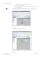
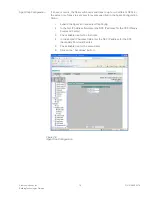
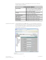
Страница 14: ... Expand the X204 2 X204 2LD icon and click on Ring 2 Select Enable ring redundancy 3 Select the redundancy mode as either HRP Redundancy Manager or HRP Redundancy Client Redundancy Manager should be selected for only one switch in the network Figure 20 Ring Redundancy Manager Configuration Figure 20a ...

Страница 15: ...uld be unchecked in the Fiber Optic Switch Web Interface Figure 21 Style 4 Settings Fiber Switch Fault Settings The Network Command Center NCC requires fault mask agent configuration agent event configuration and agent traps configuration settings to supervise the fiber optic switch using Simple Network Management Protocol SNMP Web Based Manage ment WBM is the tool used for these settings Figure 2...

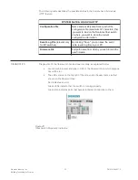
Страница 16: ...upply should be unchecked and the fiber optic switch wired to M1 L1 power line Figure 23 Fault Mask Settings Redundant Power Lines and Ring Redundancy enabled If PAD 3 or PAD 4 is used then Redundant power supply must be checked at Fault Mask and should be wired to M2 L2 on the switch Power Line 1 and Power Line 2 should be checked for monitoring ...

Страница 17: ...ect Enable Link Down Monitoring for the used Ethernet ports that have an Ethernet connection on the fiber ring 5 Select Link Up Monitoring for unused ports to supervise unauthorized connection to the fiber ring 6 Click on the Set Values button Agent Configuration This dialog allows you to select which agents are to be enabled 1 Click on the Agent icon 2 Select the following Agent Enabled Features ...

Страница 18: ...limited to specific values or not used at all as indicated below S G N I T T E S T N E V E T N E G A e r u t a e F m a r g o r P n o i t p O r o n i d e t t i m r e P N Y 4 6 8 L U s g n i t t e S e l b i s s o P s g n i t t e S t n e g A p a r T 4 6 8 L U n i d e t t i m r e p s g n i t t e S t n e g A g o L 4 6 8 L U n i d e t t i m r e p t r a t S m r a W d l o C Y d e k c e h c n u d e k c e h...

Страница 19: ...s specified in the Agent Configuration Menu 1 Expand the Agent icon and select Trap Config 2 In the first IP Address field enter the NCC IP address for the PCC Primary Command Center 3 Check Enable trap for the first item 4 In the second IP Address field enter the NCC IP address for the SCC Secondary Command Center 5 Check Enable trap for the second item 6 Click on the Set Values button Figure 26 ...

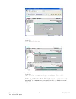
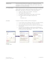
Страница 20: ...n P N 315 050537 3 20 FIRMWARE UPDATE System Version Numbers To get to the following dialog box click on system then Version Numbers Figure 27 System Version Numbers Multimode Fiber Optic System Version Figure 27a Single Mode Fiber Optic System Version ...

Страница 21: ... h c t i w s r e b i f e c n a l a c S n o i s i v e R e r a w d r a H e c i v e d e h t f o n o i s r e v e h t s y a l p s i D s s e r d d A C A M e c i v e d e h t f o s s e r d d a C A M e h t s y a l p s i D r e b m u N B F L M e c i v e d e h t f o r e b m u n r e d r o e h t s y a l p s i D r e b m u N l a i r e S e c i v e d e h t f o r e b m u n l a i r e s e h t s y a l p s i D System Sa...

Страница 22: ... l i F g o L t n e v E y l n o t n a v e l e r s e h c t i w s T R I r o f t n e v e e h t e v a s n a c u o y e v a S g n i k c i l c y B C P r u o y o t e l i f g o l t n e v e e l b a t e l i F e r a w m r i F e h t d a o l o t h s i w u o y h c i h w m o r f e m a n h t a p l l u F e r a w m r i f w e n DIAGNOSTICS Diagnostics of the fiber switch can be done remotely as explained below Launch ...

Страница 23: ... of IP address range is 192 168 1 1 192 168 1 64 XNET Address Node ID range is 1 64 NCC database requires Node IDs from all nodes in all XLS systems NCC requires Node IDs and IP address information from NCC Fiber Optic Switch Initial Setup To setup the IP address of the NCC execute the following steps From the desktop click Start Network Connections Local Area Connection From the Local Area Connec...

Страница 24: ...ck on Add or Remove Windows Components 3 From Windows Compon ent Wizard window scroll down to Management Monitoring Tools and click Details Figure 31 SNMP Protocol Setup Add Or Remove Program 4 From the Management and Monitoring Tools window select Simple Network Management Protocol and click OK 5 From the Windows Components Wizard window click Next and follow instructions until installation is co...

Страница 25: ... following are checked Control Vectoring TCP IP used for NCC link Inhibit automatic data base exchange Click Done when finished Figure 33 NCC System Settings At the NCC launch the Network Node Map to view the current configura tion by clicking More Setup Network from the NCC interface This is a list of all XLS MXL nodes and NCCs in an entire complex that are communicating with the NCC To add a new...

Страница 26: ... the following steps refer to Figure 35 Click on the Add button Next type in the Node number to match the Node number from the Zeus configuration 1 64 Add a Node Name Choose NCC G as the NodeType Choose the Type of NCC G Node as either This Unit or Remote Unit Type theTCP IP Network Address as the IP address of the NCC PC Click the Save button ...

Страница 27: ...ode Adding An XLS To add an XLS node complete the following steps refer to Figure 36 Type in the Node number to match the Node number from the Zeus configuration Add a Node Name Choose XLS as the NodeType Choose the Node numbers of the NCC as the Default NCC G Control Setting Click the Save button ...

Страница 28: ...ding An XLS Node Fiber Optic Switch Setup A new button is added in the NCC s Network Node Map window for the Ethernet Multimode Fiber Switch as shown in Figure 37 Click on Fiber Optic Switch button to open the Fiber Optic Switch List window to add delete or update a Fiber Optic Switch ...

Страница 29: ...ll pop up to notify the user that the address is not a valid address 3 Add the IP address of the switch as the assigned IP address Assign IP Address 4 For the Ring Redundant Manager select either Master or Client to agree with the setting Ring Redundancy Manager 5 Click the Add button to complete the changes or on Cancel to leave the settings as they were Figure 38 Adding A Fiber Optic Switch Dele...

Страница 30: ...ate a switch follow these steps 1 Select the switch you want to update from the Fiber Optic Switch List window 2 Click on the Edit button or double click on the selected switch on the list 3 An update window displays as shown in Figure 40 except that the address field is disabled 4 You can update the IP address and or the Ring Redundant Manager setting 5 Click on the update button to complete the ...

Страница 31: ...needs Such a security concept may result in additional site specific preventive action to ensure that the building comfort fire safety security management or physical security system for your site are operated in a secure manner These measures may include but are not limited to separating networks physically protecting system components user awareness programs defense in depth etc For additional i...

Страница 32: ...ng Technologies Division Florham Park NJ Siemens Canada Ltd 1577 North Service Road East Oakville Ontario L6H 0H6 Canada P N 315 050537 3 Document ID A6V10320072 THIS PAGE HAS BEEN LEFT INTENTIONALLY BLANK Doc No A5Q00064184A 02 ...

Отзывы: